N95 Respirator

TL;DR: I made a working respirator using a small stockpile of N95 replacement filters I have… However, since a local hospital has the appropriate adapters and real respirators, for the greater good, it makes the most sense for me to simply donate my materials.

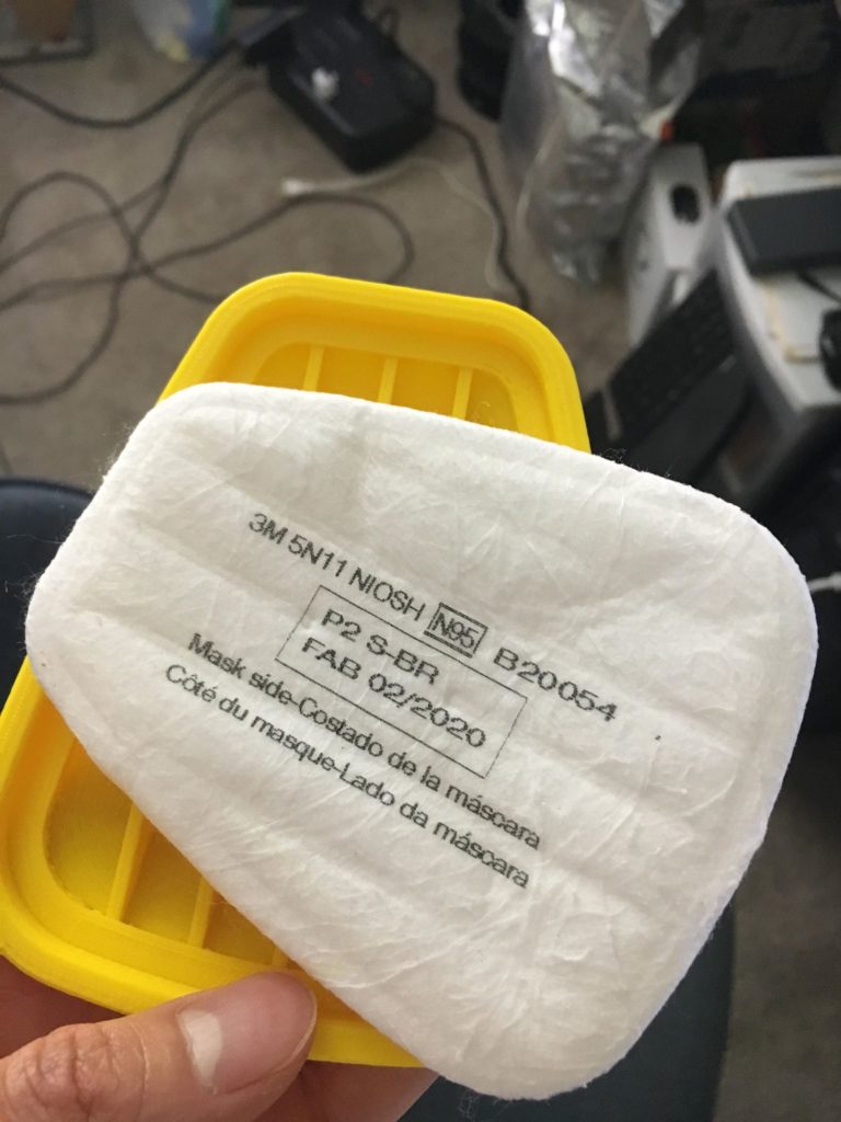
Two weeks ago, I completed the design of, and successfully tested a prototype N95 respirator. Before everything was sold out, I managed to buy a small stockpile of about forty 3M 5N11 particulate filters, typically used for industrial purposes. Unfortunately, I didn’t find any of the requisite adapters nor compatible respirators.

Luckily, what I did find was this great project called S.A.F.E (self-assembly filtration unit for emergencies) from the Medical University of South Carolina (MUSC) (https://web.musc.edu/innovation/covid-19-innovation/safe-cartridge-system-and-masks) to use as a starting point for my own design. In the original design, MUSC recommends using part of a furnace HEPA filter as the filtering material inserted in a replaceable cartridge system. What I believe was the true key to their design, however, is the inclusion of a simple one-way valve. The valve makes it easier to breathe out, prevents excessive CO2 buildup, and extends the life of the filter, but it does not prevent the user from spreading COVID-19 if they are already infected.

To speed up the printing process (and thereby the prototyping and fit-checking stages), I broke the system into three main components:

  1. The mask – this remained untouched from the original
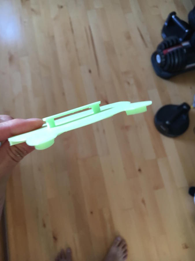
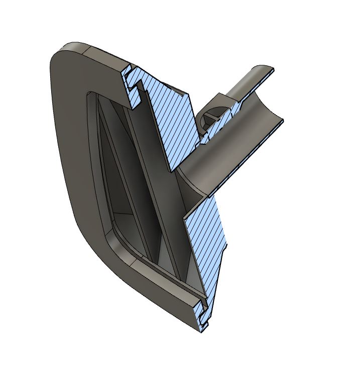
  2. The tube – This component was originally built into the cartridge, and attaches the filter to the mask. The tube also houses the one-way valve, which I thought was a particularly high-risk feature, so I wanted to be able to test it separately.
  3. The cartridge – I needed to replace the HEPA filter design to fit 5N11 replacements.

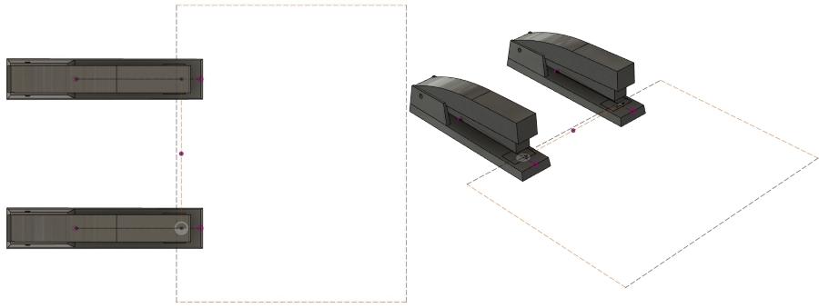
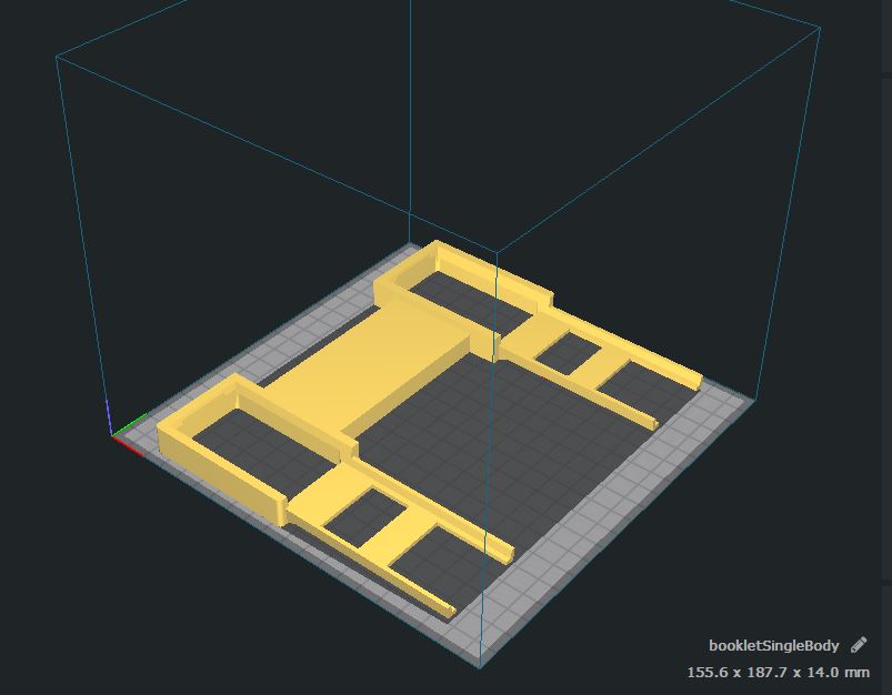
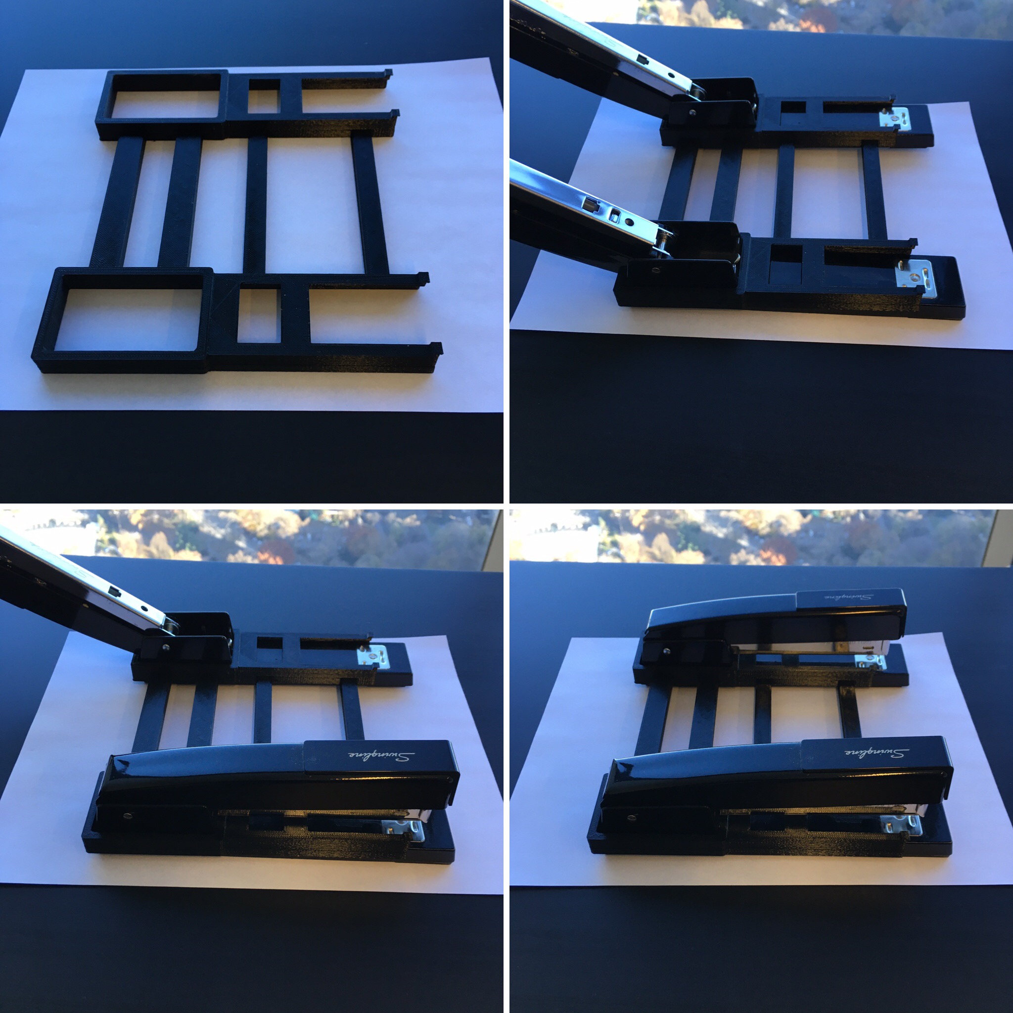
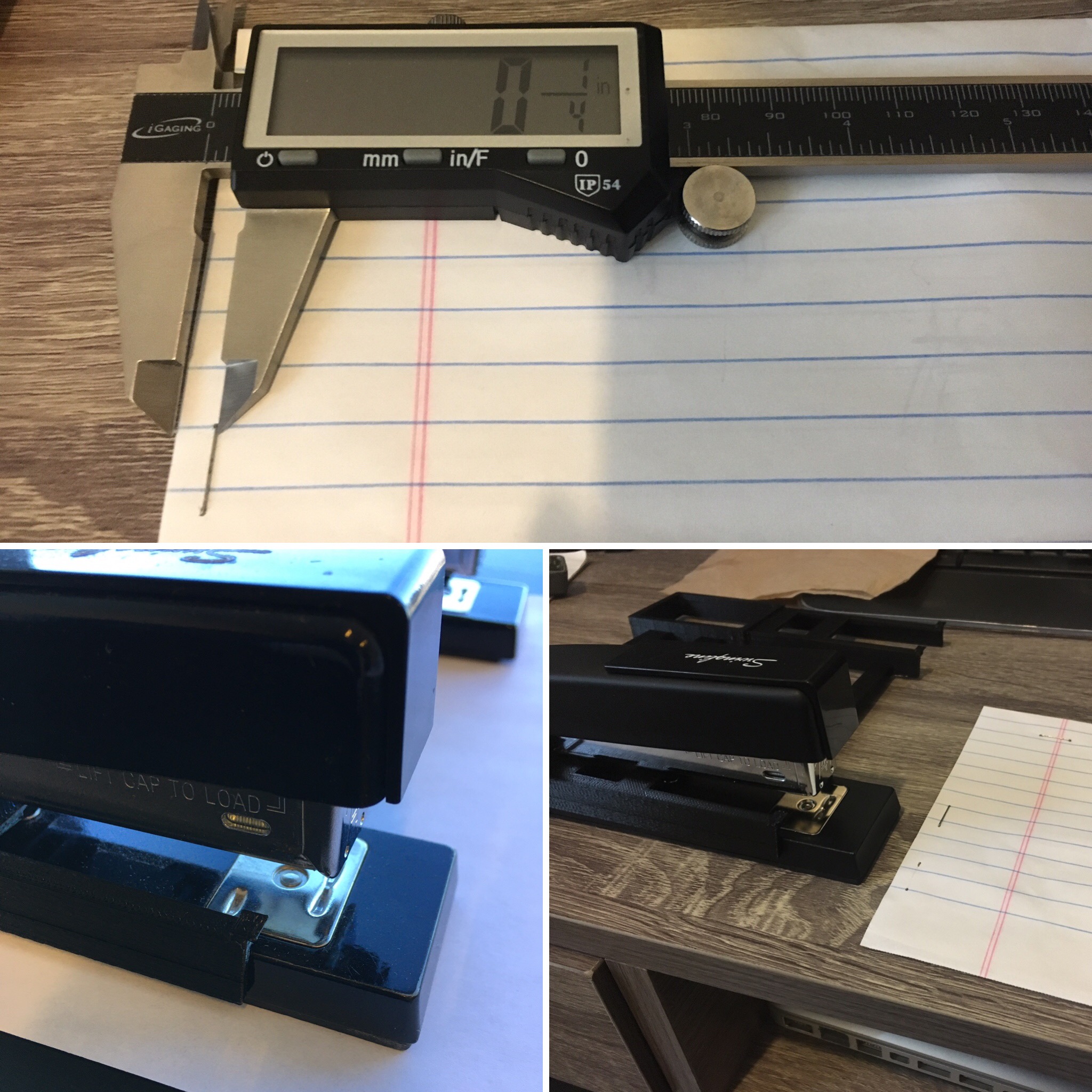
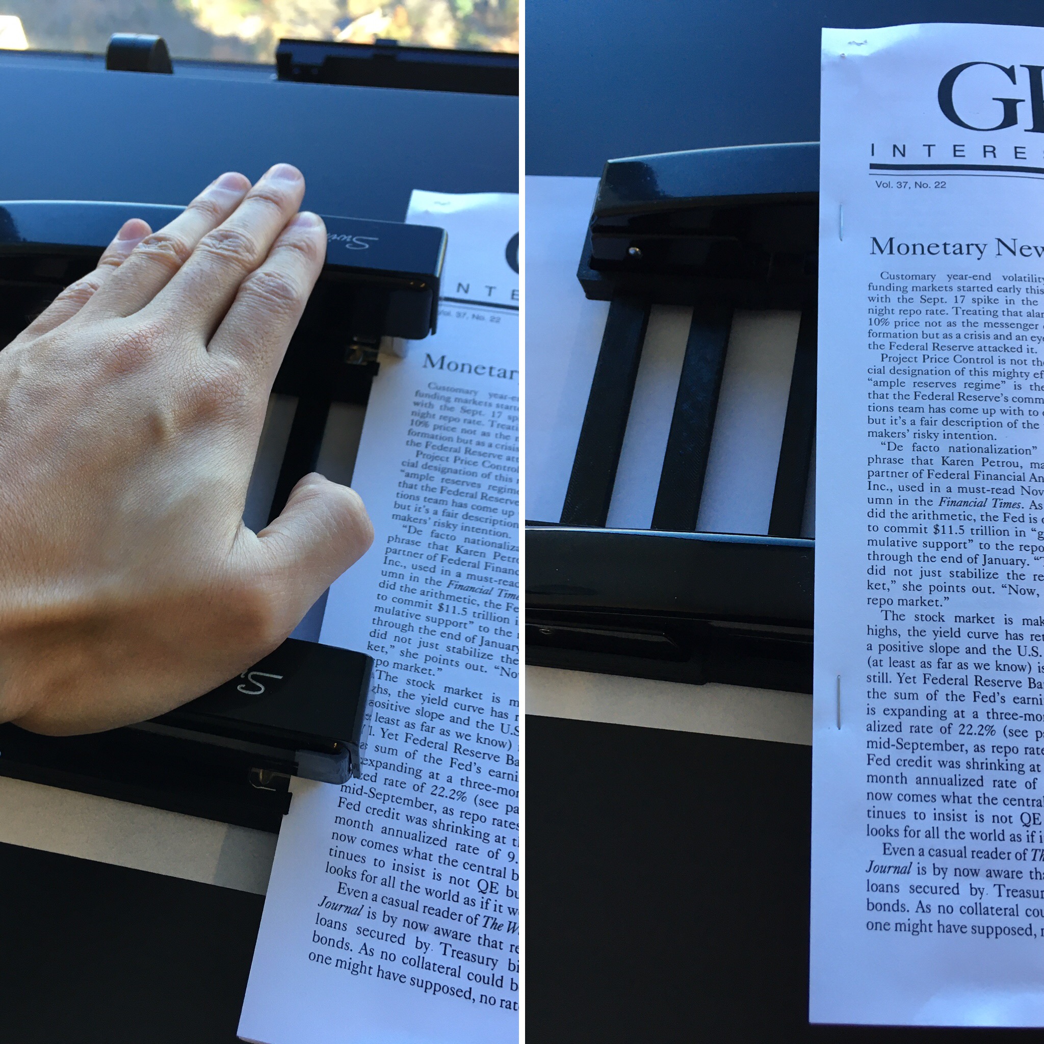
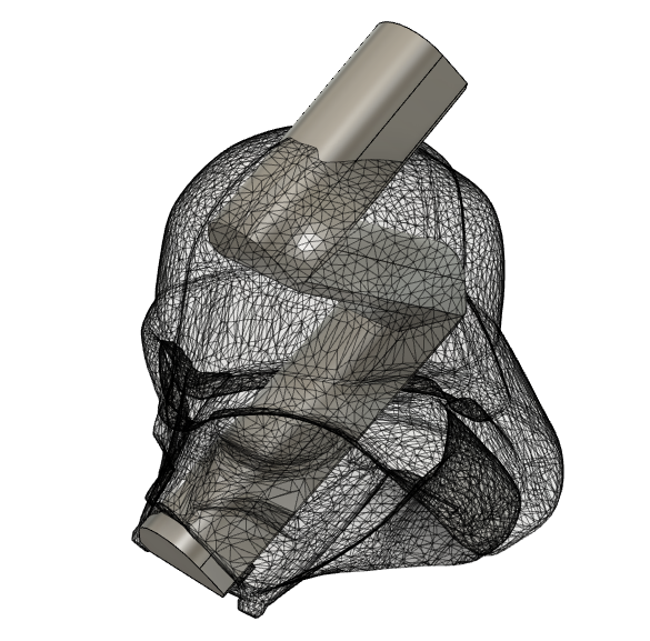
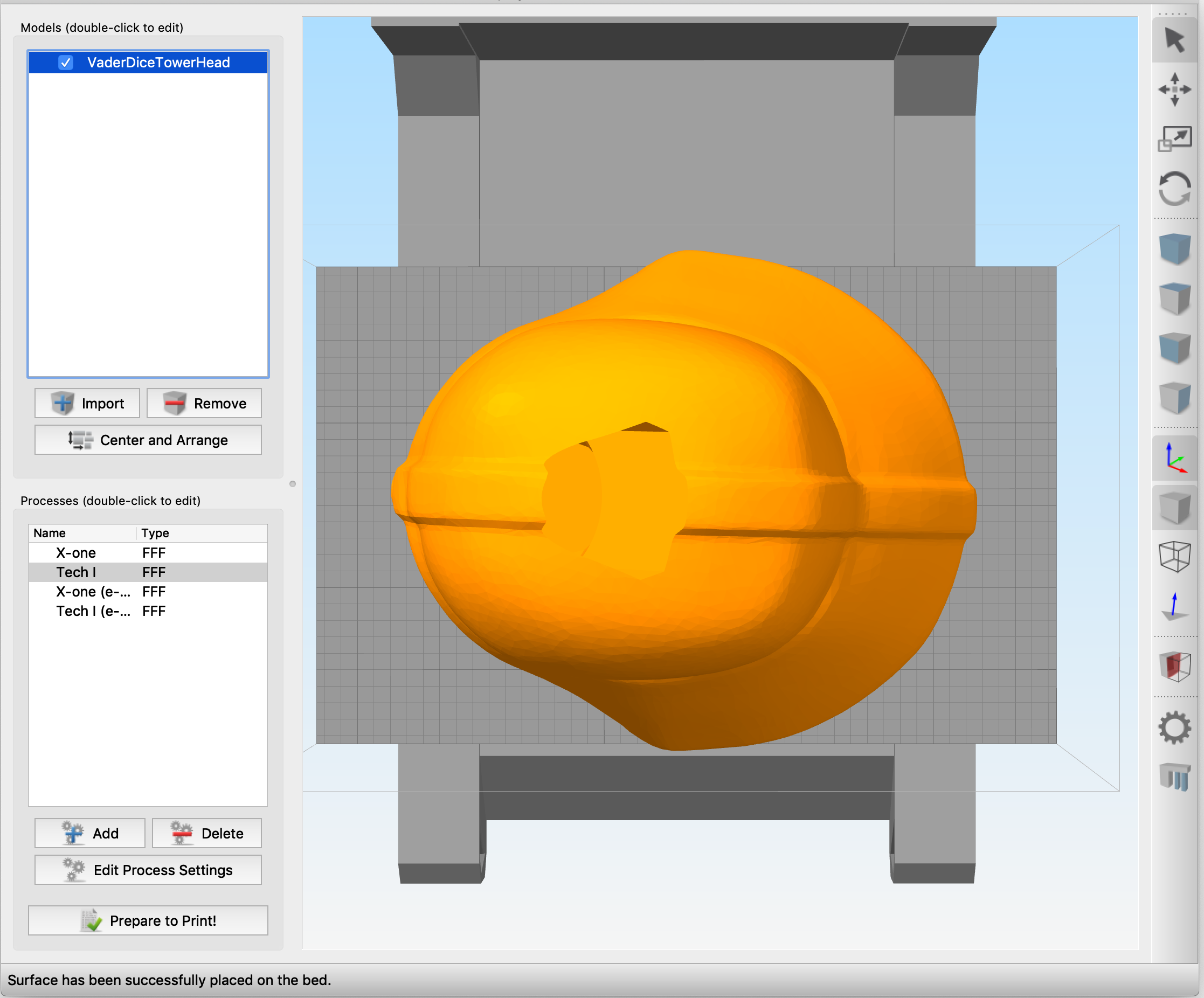
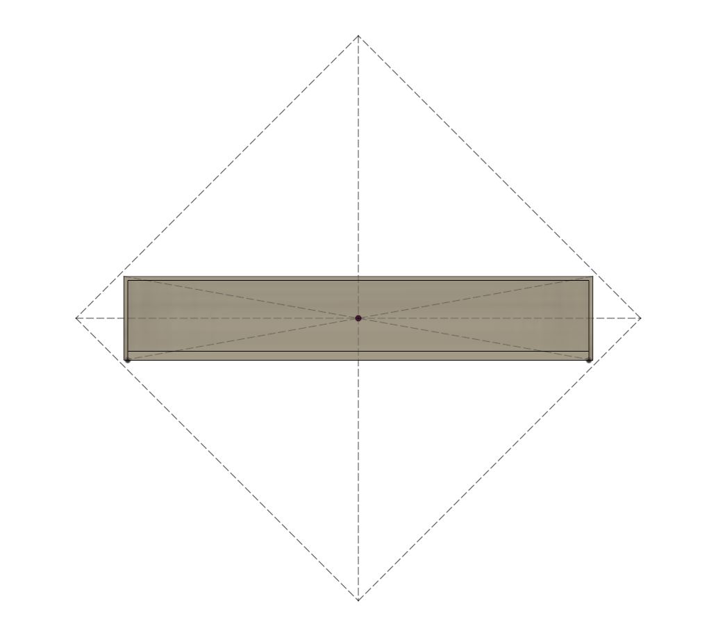
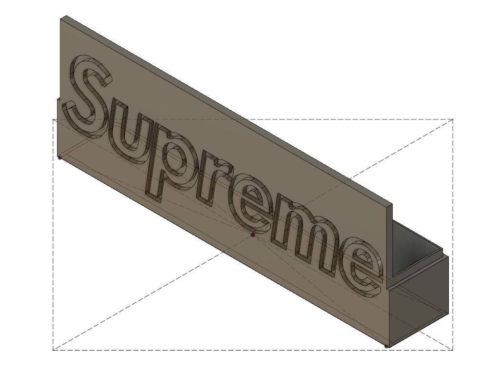
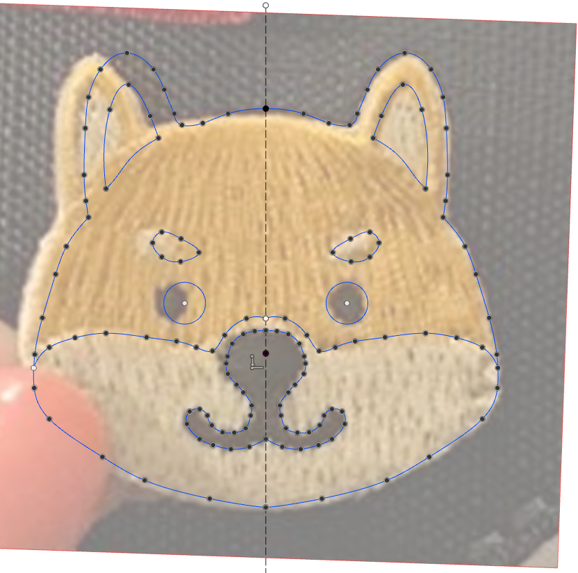
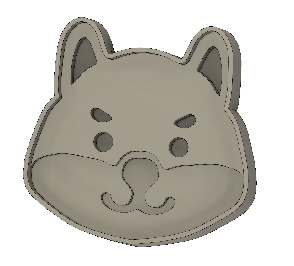
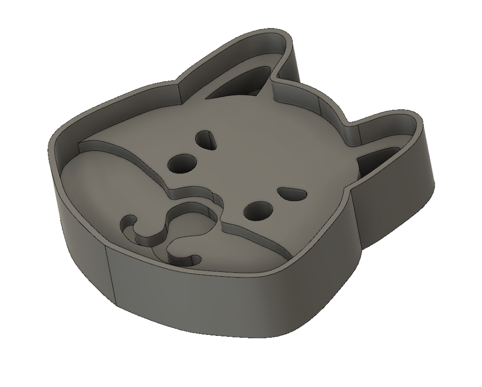
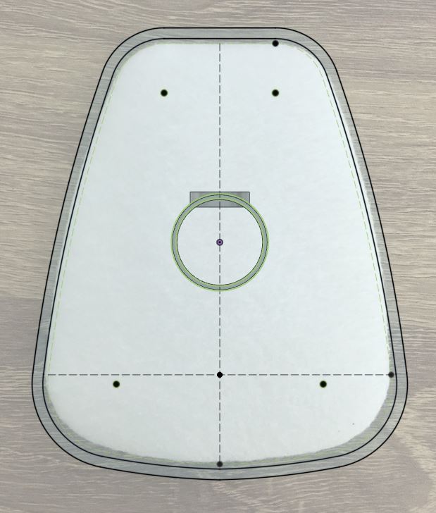
Since the mask needed no modifications and changes to the tube were minor, I was free to focus my energy on creating a cartridge to fit filter replacement pads. To be honest, even this was a fairly straightforward design job… I took a few measurements of my filter and made a simple enclosure, making sure that the tube would fit into the back. One neat trick I employed to check my fit before printing was that I took a photo of my pad and imported it into my design software to ensure all my geometry looked correct.

Checking dimensions of the part against a photo

While I originally intended the design to be a snap fit to make it easier to swap out the 5N11, I decided that simply sealing everything in place with hot glue, and turning the cartridge into a single-use item would be safer. It is simply much harder to guarantee a seal if end users are the ones making changes.

Cross-sectioned view of the new cartridge system

The tube only took about half an hour to print, so I made that first to test the valve. The S.A.F.E. design called for the use of heavier rubber for the flap, but the only material I had available were thin inspection gloves. Luckily, the design was robust as-is! However, since my membrane material was much thinner and tended to curl, I paid extra special attention to ensure the curl direction defaulted to the closed position. Next, I made the filter cartridge. Since I had checked all my dimensions electronically before, the parts fit together perfectly on my first try—yay! I hot glued a filter in place to make sure the only path for air was through the filter pad itself.

Printed cartridge with a real N95-rated filter

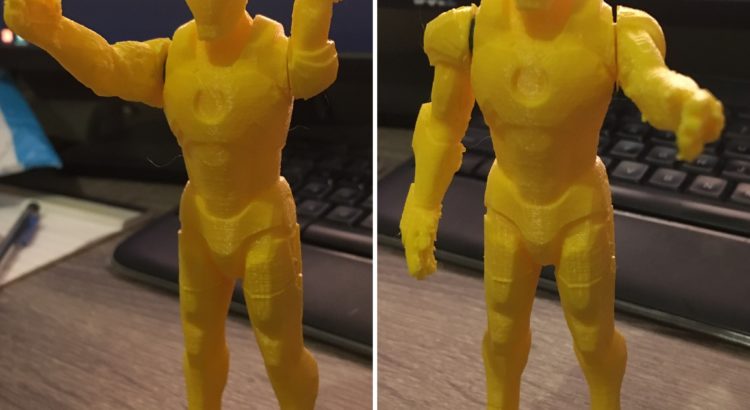
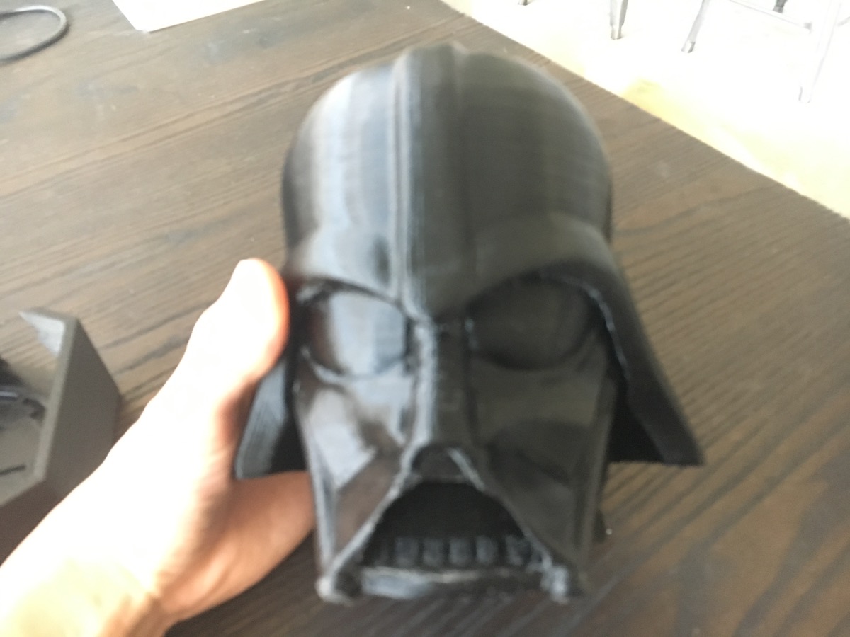
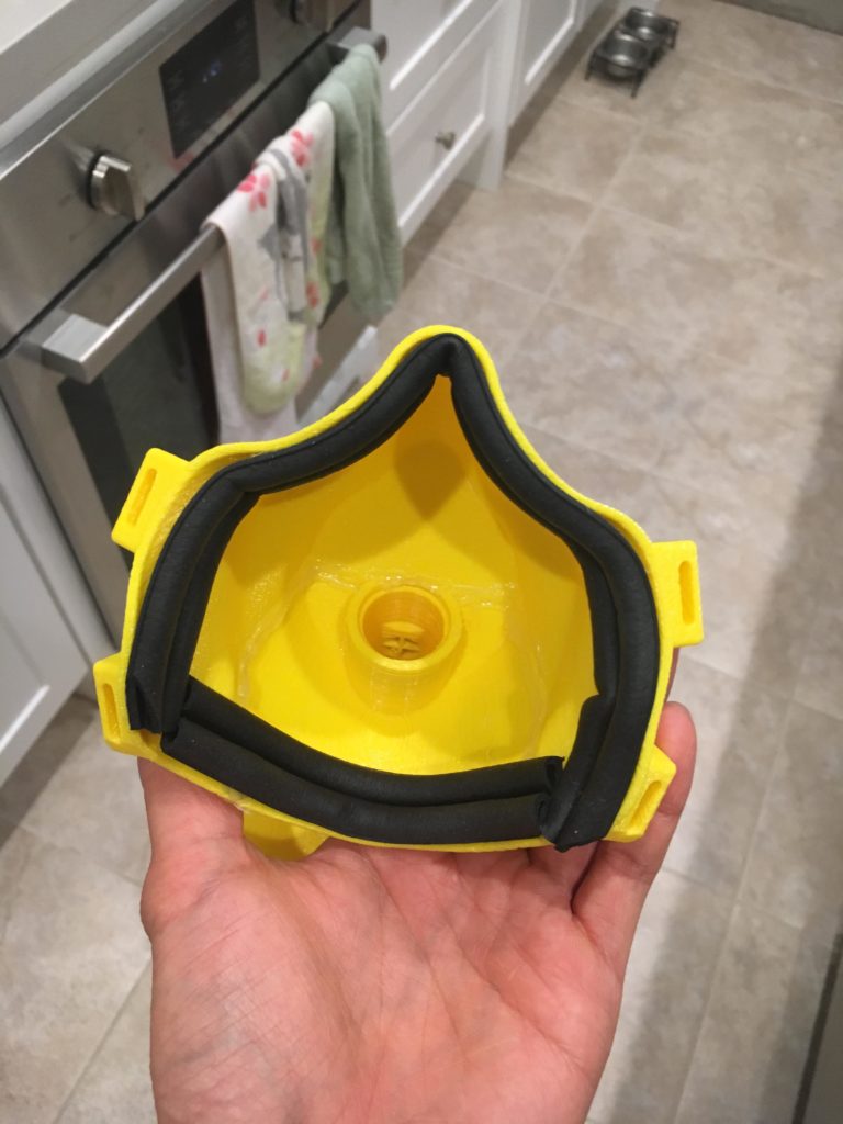
Since the mask took hours to print, I made it overnight. Unfortunately, sometime in the middle of the night, my nozzle clogged a bit and/or my extruder skipped a few steps. This resulted in some underextruded and weak layers, which caused the mask to break as I removed it from the print bed and cleaned up support materials. However, since the breaks were clean, I was able to fix the mask in a quick and dirty way by simply smothering the interface with hot glue. I then attached some rubber material used for sealing windows to the inside of the mask to ensure I could get a tight airtight seal on my face.

Rubber window seals were used to create an air-tight fit

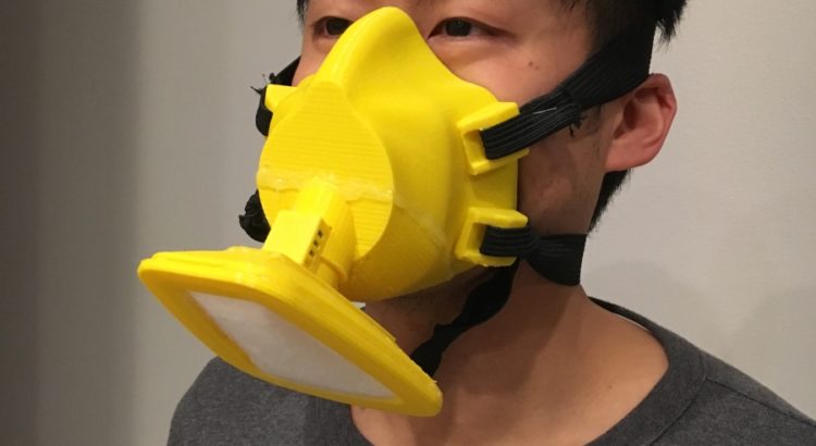
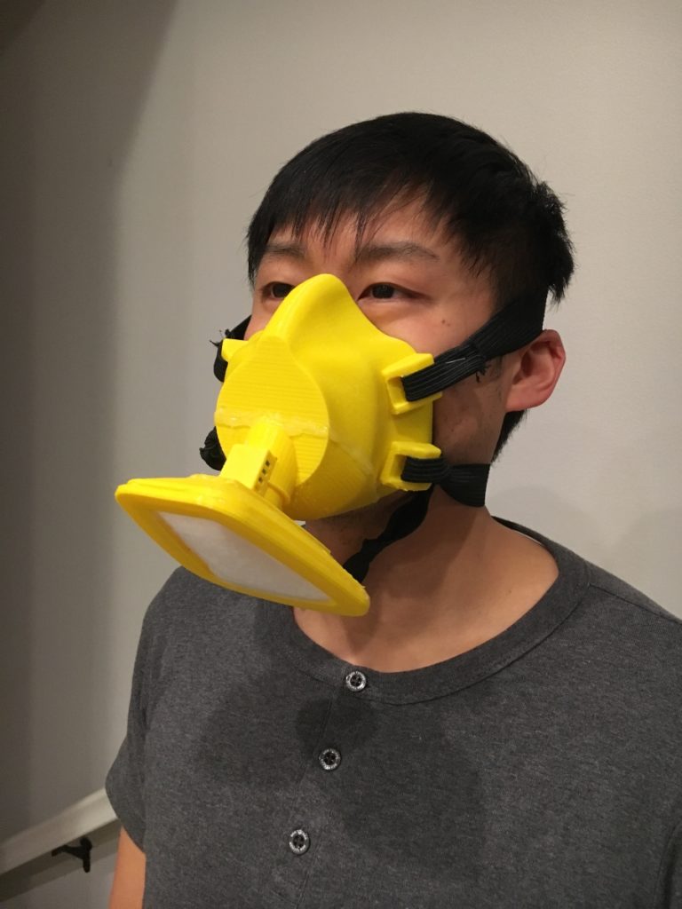
Assembling the mask was simply a matter of attaching the cartridge with tube into the corresponding hole in the mask. I put the mask on and breathed in and out to ensure the valve operated as intended. Then, I did a vacuum test—I covered the filter with a sheet of plastic, and breathed in extra hard… and… success! I was able to hold the plastic up, demonstrating no leaks in my mask!

Successful test of 1-way valve!

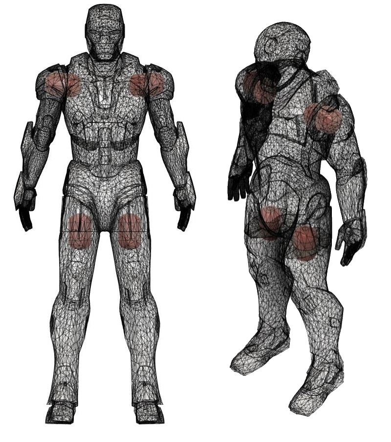
Despite some initial success, I quickly realized there were some potential issues with my mask design. First, the positioning of the filter is non-ideal for healthcare workers. Although the filter is out of the way for the doctor, it is facing a potentially exposed area where it is super easy for a patient’s cough to cover the filter itself. Second, my design lacks any sort of exterior grating to protect the filter. Regardless, I saw the two units I did make as a huge success.

An actual N95-rated respirator!

As an engineer, I really love designing and making stuff. However, in this situation, I realized that if any hospitals actually had the real adapters and respirators to pair with my 5N11 filters, then the filters would be better utilized as donated goods. I contacted a few hospitals in my area, and UCI said they could accept them.

Despite giving away my filter materials, not all is lost for me in terms of making pseudo n95 masks! The NIH actually approved of this design for clinical use: https://3dprint.nih.gov/discover/3dpx-013429 and both Keck (USC) and Cedars Sinai accept this alternative N95-esque design:  https://blog.crashspace.org/covid/

As an aside, now that I have two printers running, my output has tripled (my 2nd printer has a bigger build area than my first), and with bigger nozzles coming in, I expect my output to increase again to *FOUR* times what I started with.

Hope everybody stays safe and healthy out there!

Booklet Maker

TL;DR: I designed and printed a booklet maker for a friend.  

Instead of completing the Inktober challenge I spent the month of October designing and printing gifts for friends… and I spent November writing about them, haha. I posted about a Darth Vader dice tower here, an Ironman figurine here, and the third project I completed is this booklet maker.

My friend Will reached out for help solving a specific problem: he likes to staple papers into booklets, but needed a way to make them more easily and consistently. We went back and forth with some requirements (number of sheets at a time, staple placement, etc.), he drop shipped a stapler to me, and I started designing.

I began by modeling the classic Swingline 747 stapler from caliper measurements. I needed an accurate stapler model to ensure a good fit for whatever 3D printed part I would ultimately design. Capturing the draft of the side and determining the clearance available during stapler actuation was of paramount importance, so I created the stapler in two components and added movable mates.

Creating the stapler model in two components to allow for assembly mating features proved very useful in determining space available for designing

For this project there were advantages to taking a top-down design approach. In a new part model, I created a layout sketch to place the staplers per the desired specifications 6 inches apart on a line ¼ inch away from the left margin.

Taking a top-down design approach ensured the requirements were met from the beginning. All dimensions were driven from where the staples ultimately need to go.

With the staplers fixed in place, I focused my attention on the design of the main paper retention body. The trickiest part of the design was creating an attachment method that keeps a clear path for the stapler head to reach the crimp area.

After completing a test print to check the fit, I made a few adjustments to the paper backstop height, mirrored the body and connected the two halves with beam extrusions. Pictures speak louder than words, so here’s the build gallery:

Will tells me he’s very happy with the results, and I couldn’t be happier myself.

Action shot! It might take a bit of time for the gif to load

Ironman Figurine

TL;DR: I uploaded my first Thingiverse share! I improved the design of an existing Ironman model by adding pegs to allow for articulation and adhesive-less assembly.

I went on a work trip to Phoenix in early November. Fortuitously, my best friend growing up lives there and loves Ironman like I do. I decided to squeeze in a quick design and print project to gift him.

I found a decent looking Ironman figurine on Thingiverse here. This model is actually a remix of another project—the remixer made the part easier to print by separating the limbs. While this was a good step forward for printability, I further improved the design by adding pegs between the extremities and the main body:

The pegs I added are in red. They allow easy assembly plus articulation.

The boolean tools available in Fusion360 make it incredibly easy to complete simple changes like this. I undersized the peg in the CAD model, but small variations in print settings and nozzle wear and tear make perfect fits a bit tricky. In fact, it took me a few tries to get the pegs working really well, but the prints were short, and the results were worth it:

Assembly in process

Given that this project originated directly on thingiverse, I thought it was only right to give back to the community and share my very first remix here: https://www.thingiverse.com/thing:3998580. The number of views and downloads of this model pleasantly surprised me, given the simple and obvious nature of the change I made. I’ll probably consider sharing more stuff going forward… we’ll see ¯\_(ツ)_/¯.

I think the assembly with articulation turned out pretty well—the yellow looks vaguely gold-ish, so the only thing missing is some red paint:

He just needs a paint job

Vader Dice Tower

TL;DR: I made a villainous dice tower for a friend’s bday, combining two of his favorite things—Star Wars and board gaming.

October was a pretty busy month for me with work and fantasy football both ramping up. However, I’m very happy I was able to get some design and project time in. My friend Nick’s birthday was earlier this week, and I wanted to make him something practical yet personalized. Anybody who knows him at all knows how much he loves both board games and Star Wars, so to me, printing a Darth Vader dice tower was simply a no brainer.

For those of you who may not know, a dice tower is a very simple device to ensure fair rolls while keeping dice from flying all over the place and messing up stuff on the table. Dice towers can take on a wide variety of shapes and sizes. All that is really needed is some sort of aperture at the top to put dice in, a path which randomizes spins, and a tray to collect them at the end.

Before I started designing, I did a quick search on thingiverse and other 3d print sharing sites to make sure I wasn’t completely reinventing the wheel. I found a few Vader dice towers, but to be honest, I didn’t think they were very good in terms of amount of detail and general aesthetics. I was fortunate to find a great model of Darth Vader to begin with: https://www.myminifactory.com/object/3d-print-star-wars-darth-vader-30-cm-tall-60500.

Essentially my plan was as follows:

  1. Reorient and resize the head to maximize the print area on my bed.
  2. Create the dice travel path leading from the top of the head out of the mouth.
  3. Subtract the path model from the head model.
  4. Create a tray to catch the dice
  5. Print the parts
  6. Ship it

Parts 1-4 went incredibly smoothly all within Fusion 360. I successfully printed a ¼ size test part to ensure the path I created could be printed without any internal support structures to minimize post processing work. Unfortunately, I then ran into printer issues I had never previously encountered…

My Monoprice Maker Select Plus (aka Wanhao Duplicator III Plus clone) has been a workhorse without any major issues for years now. Of course, she decided to act up when I was up against a deadline since birth dates are immutable. My printer would randomly stop working and send bed temperature errors before rebooting. I pinpointed the problem to the thermistor on my print bed, but I didn’t have time to mess around. Luckily for me, my neighbor across the street literally has a print farm in his bedroom (15 machines and counting) so I was still able to get the parts made on time. The only unfortunate thing is that his machines are smaller than mine—so he had to scale the size down by 5% to get them to fit. (I found out later that the fix I needed on my printer was incredibly basic: the kapton tape holding the thermistor to the bed loosened over time, thus the printer received intermittent temperature readings.)

Luckily, the 5% reduction in size did not severely diminish the part’s functionality:

It works! May the Force Be With You!

I’m incredibly happy with the results of this project. I enjoyed the challenge of modifying an existing mesh to create a new, meaningful, and practical object. Even though UPS spoiled the surprise by giving Nick a notification about the arrival of a package sent from my area, and the package arrived late, I’m pretty sure he was very pleased upon arrival.  

Thanks for making it to the end of this post—here’s an incredibly sparse build gallery:

Supreme EL Box

TL;DR: For my friend Teddy’s birthday, I made him a hypebeast worthy (if I do say so myself) Supreme EL box.

My good friend Teddy is one of the biggest hypebeasts I know, so I wanted to make something he would like. I went back to the EL wire well again for this project (see: headbands https://www.andrewpip.com/2019/03/28/el-wire-lighted-headbands/ and sign <https://www.andrewpip.com/2019/04/07/faux-neon-signage>). However, I needed to dig into my paint supplies dating all the way back to my Iron Man Mask (https://www.andrewpip.com/2018/05/06/infinity-war-masks).

Conceptually, this project was relatively simple:

  1. I made a box.
  2. I cut some channel shaped holes in the box.
  3. I painted the box.
  4. I put my wire through the box.
  5. I gave Teddy the box.

For this project, honestly I think the gallery will explain things better than I can in words, so here it is (it looks nicer if you click to open the full-sized images):

Faux-Neon Signage

TL;DR: For my friend Gina’s birthday, I made her a faux-neon sign to decorate her new condo with. I ended up making a few different versions of this sign and through the process, I learned several useful tricks to speed up vector image modifications, which will definitely make it easier for me going forward. 

I continued playing with el wire since I bought so much for my headband project. Since my friend’s birthday was coming up, I figured it was a great opportunity to make something cool with it. I decided to make a faux-neon sign reading “Mama G’s House”.

I started by searching for neon sign fonts on google and downloaded a few to try out including “Warnes”, “La Patio Script”, “I am online with u”, and “Fenotype Neon”. All of them were free to download, but not all of them were free for commercial usage, which is fine for this project as I’m not selling it.

The first prototype I made used Warnes as the base font. I really liked how the letters all connect at the bottom. However, I needed to do a bit of surgery in Inkscape to connect the disparate words after vectorization:

The main modifications I made to this first font were just around connecting the letters and adjusting some of the spacing

I imported the SVG directly into a sketch Fusion 360 and resized it to ensure I had a ~3mm wide channel all over. Next, I modified the sketch to remove areas near the bottom where the lettering overlapped. In a fashion similar to what I did for the EL headbands, I extruded a positive model of the letters. Next, I needed to move the apostrophe body and combine it with the rest of the lettering. Then, I created a sketch, offset the entire object, and cleaned up the line overlapping lines created by the offset tool. After extruding the outlined body, I cut the positive lettering model out:

I reused the technique I discovered while making the EL headbands of cutting the positive channel from the main body

After slicing the STL in Cura, and waiting about 3 hours for production, the print came out pretty well:

However, with the physical model in front of me, I saw the font I used had a few issues. Primarily, although the channels I made fit the el wire, there were too many places where stringing it required a double back, which was not accounted for. Oops. Luckily, I hadn’t spent a lot of time on this, and I figured Gina could still use it as a nice decoration even without lighting effects.

The next font I tried was called “I am online with u” which had the advantage of being a single connected line. Although this font was more ideal out of the box, I still needed to tweak the vector version to make it work properly. Essentially, I just modified the “corners” of the letters to allow for more space wherever they changed direction, I adjusted the spacing between words and letters, and I moved and combined the apostrophe to overlap with the letters.

I modified this font a bit more heavily to ensure a good print. The biggest tweak was widening the letters where they changed direction so the EL wire could bend around.

My workflow in Fusion 360 was essentially identical to the one I used for the previous version of the sign: import svg, scale, and clean up sketch -> extrude a positive channel -> offset the body and extrude the outline -> use the combine tool to cut the positive channel away from the outlined body. Unfortunately, this part was a bit too big to fit on my printer in one piece, so I needed to split it into two. The split created a physical weakness which I shored up by creating a small base to hold it together and help the entire assembly stand upright.

The split was unfortunate but necessary to allow me to actually manufacture the sign. The base I made fit very well and helps keep the assembly standing too.

The print didn’t take very long—maybe about 4 hours in total for all the pieces. I was pretty happy with the results, and I think she was too 🙂

Shiba Cookie Stamp

TL;DR: I made a shiba cookie cutter/face stamp combo for a friend. As a bonus, I made a bone-shaped stamp with her dog’s name on it as well :D.

First up, here’s a photo of the completed cookie cutter, stamp, and name stamp. The overall dimensions of the stamp are approximately 3in in width and 2.75in in height. 

I received a request from a friend to design and print some stuff for her Shiba’s birthday coming up. I used a photo of her dog’s vest to use as a template I could trace with splines in Fusion 360. In my first version, I made a combined cutter and stamp by extruding various parts of the face to different heights.

While the first prototype worked on polymer clay, it was pretty clear that a few simple tweaks could make it easier to use. First and foremost, it was pretty difficult to press the stamp down since I didn’t include any holes for air to escape. Second, it was a bit difficult to remove everything from the press. Third, since I had fixed heights, the cookies the stamp made would likewise have no flexibility.

Changing to an outline cutter and a stamp for the face addressed all of the issues above and was very simple to do in CAD. The trickiest part was my desire to have a detachable handle to cut down printing time. I created mounting points for the handle by cutting holes beneath the eyes. On the stamp, I made sure to add a larger draft angle on the extruded areas to make it easier to detach from the dough.

I also made a simple name stamp. I was pleasantly surprised at how easy it was to create extruded text in Fusion. The rest of the bone shape and handle were essentially just decorative. I think the name stamp has a potential issue with the letters being too close together, but that should be something easily addressed in a future revision.