ButterBot Spotlight Lamp

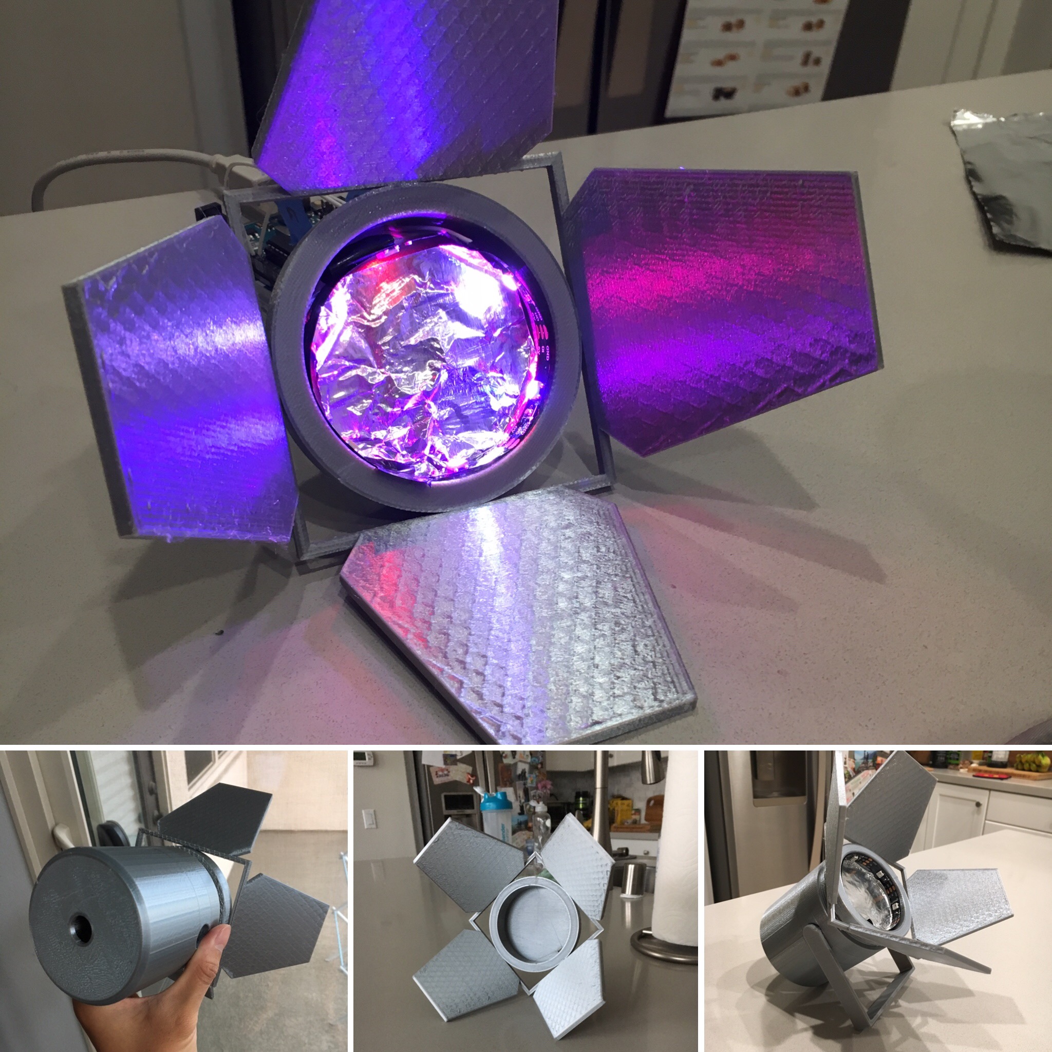
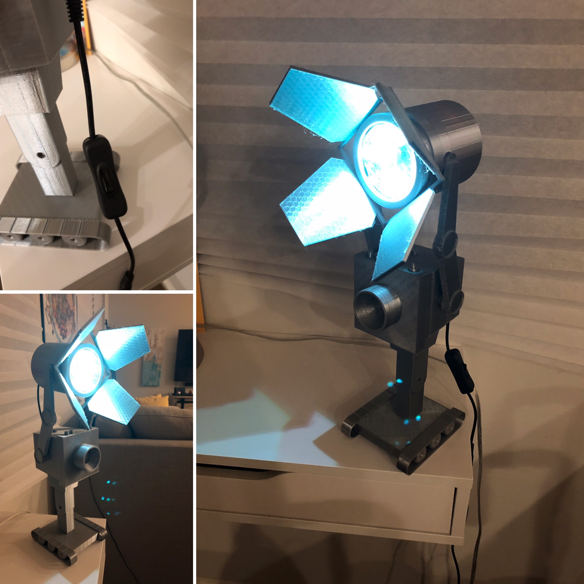
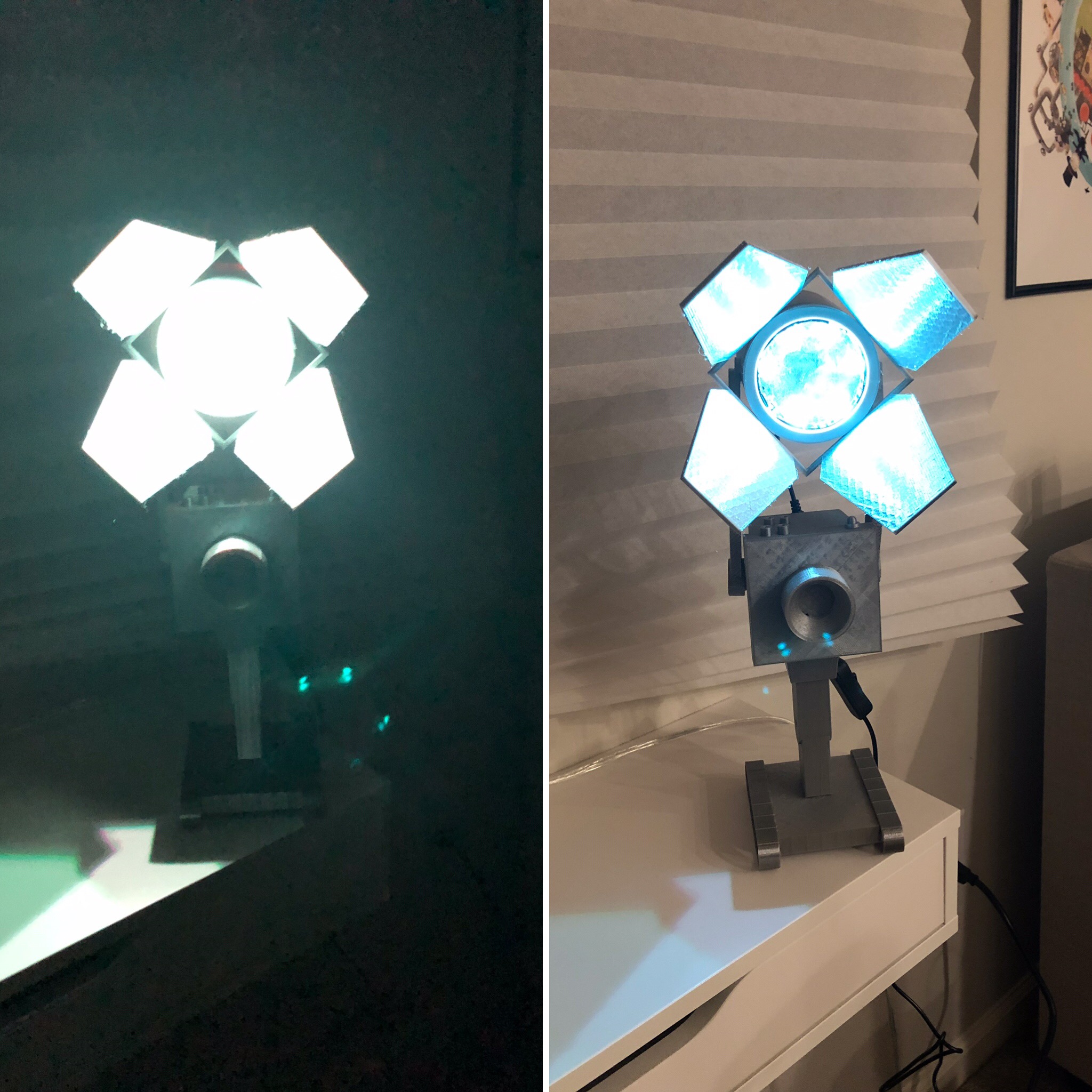
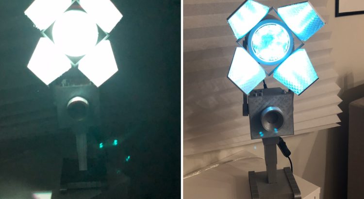
TL;DR: I made a robot whose only purpose is to hold up a spotlight… At least it’s a step up from passing butter :D. I am extremely pleased with how this guy turned out. The light is adjustable both in leaf rotation and tilt angle.

A few weeks ago, I desperately wanted a lamp for my nightstand to keep me from needing to stumble around in the dark trying to find the bed while avoiding squishing the dog after turning off the lights at night. Thus, I decided to do the most practical thing, and began designing my own.

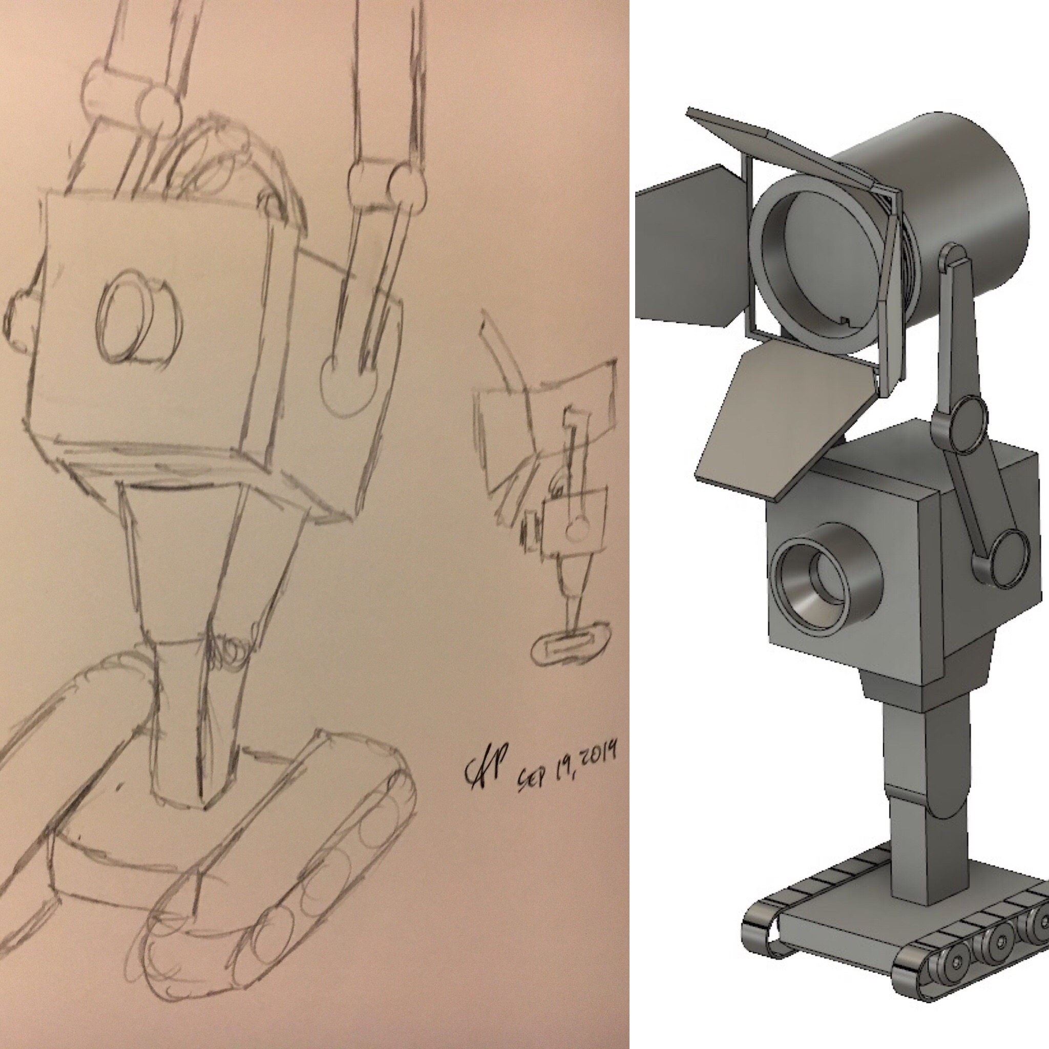
I began my design around the idea of creating something in a modular manner. I knew I wanted to have some sort of character holding up the light source, but was unsure about the specifics of what was going to be feasible, and what would be accepted by my landlord to have around the house. I landed on the idea of building around a spotlight—I like the simple shape and general aesthetics and the character-neutral nature.

Over the next few weekends, I kicked around a few ideas and asked some friends for inspiration when I had my eureka moment—THE BUTTER BOT FROM RICK AND MORTY IS PERFECT FOR THIS!!! I am a huge fan of the show, wanted to use up my silk silver plastic filament, and thought I could give this little guy a better purpose than just passing butter. Really, it was a win/win/win scenario.

I don’t have any photos detailing the electronics, but I’ve got a simple ATmega32U4-based Arduino board with a micro-USB interface. I found this awesome inline DC jack power switch and paired it with an even cooler DC jack to micro-USB cable to provide power and add the ability to turn the light on/off.

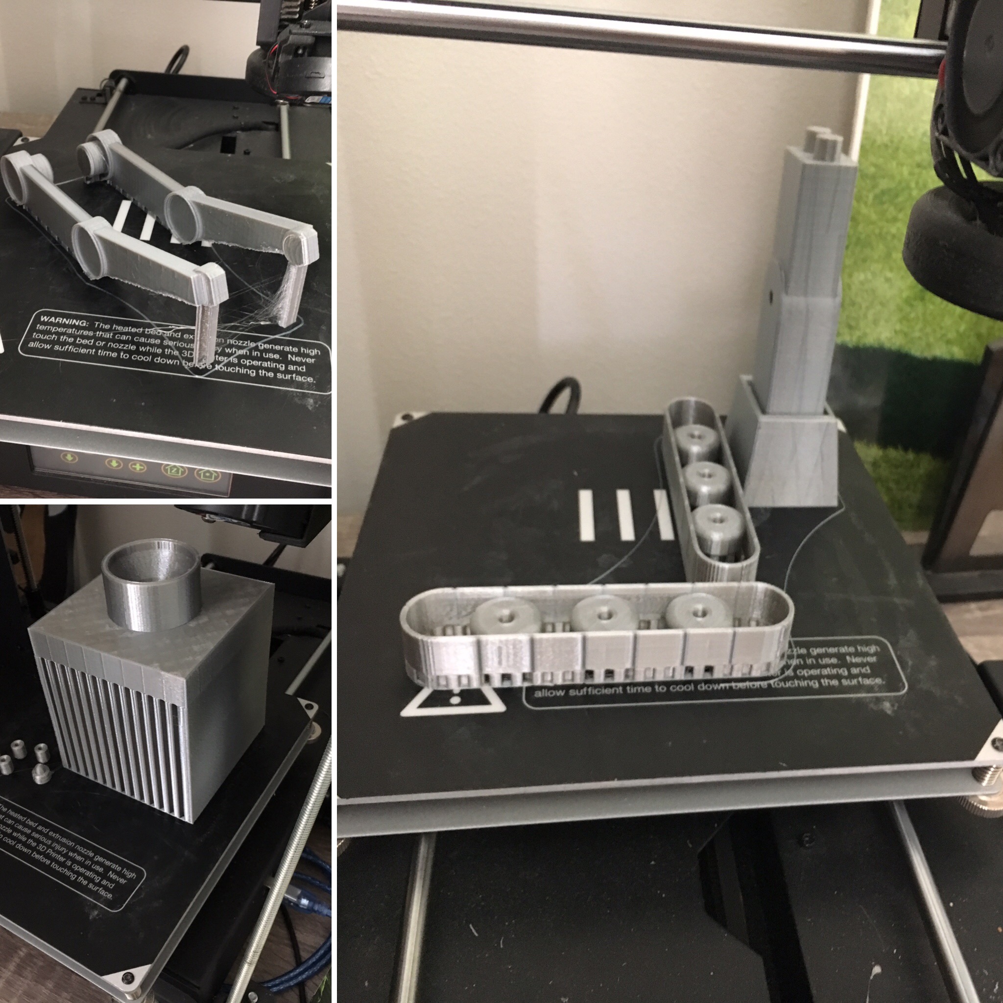
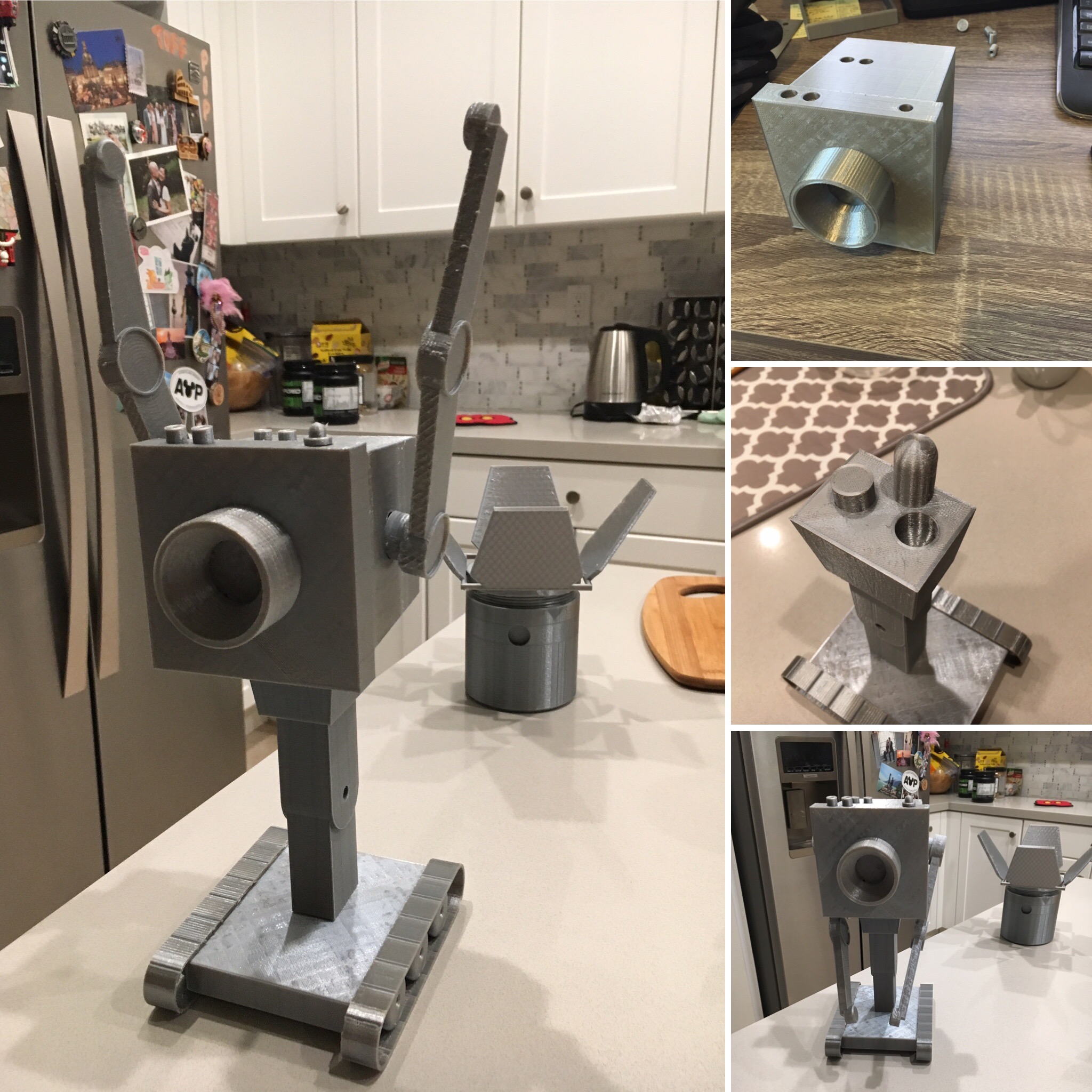
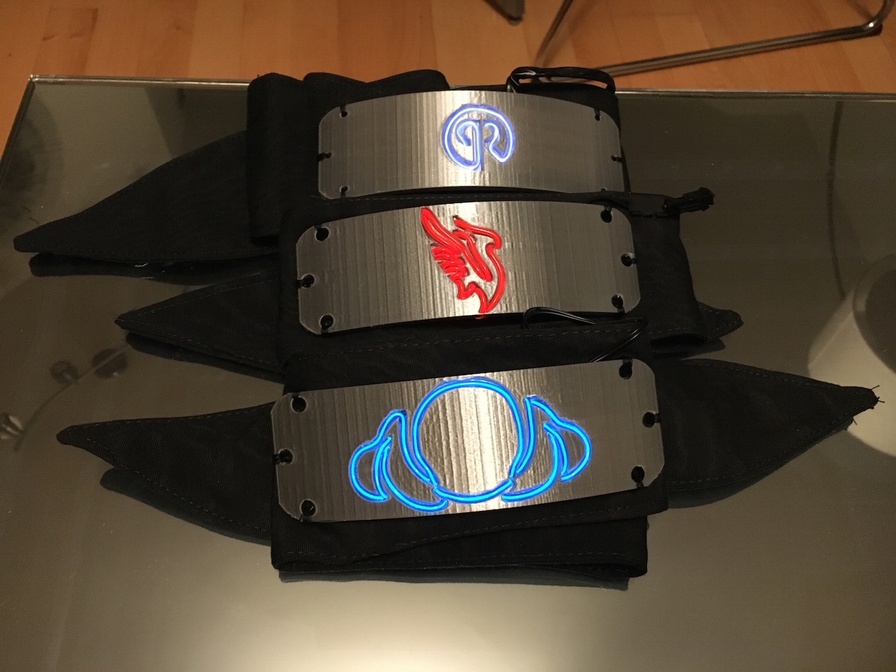
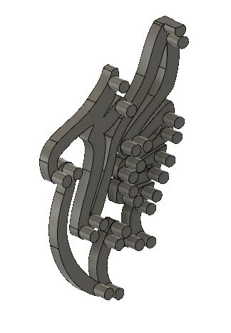
Designing and implementing my idea was relatively straightforward after deciding what to build. The trickiest part was designing the parts in such a way so they could be broken up and printed in different jobs—the overall size is roughly 7” x 8” x 18” (although the 7” width can change depending on how the spotlight leaves are oriented, and the height can change depending on the tilt angle). I am particularly proud of my insight of creating a domed peg to enable the printing of the main body without the need for supports.

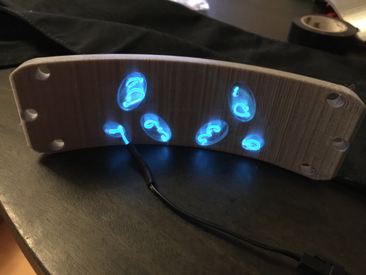
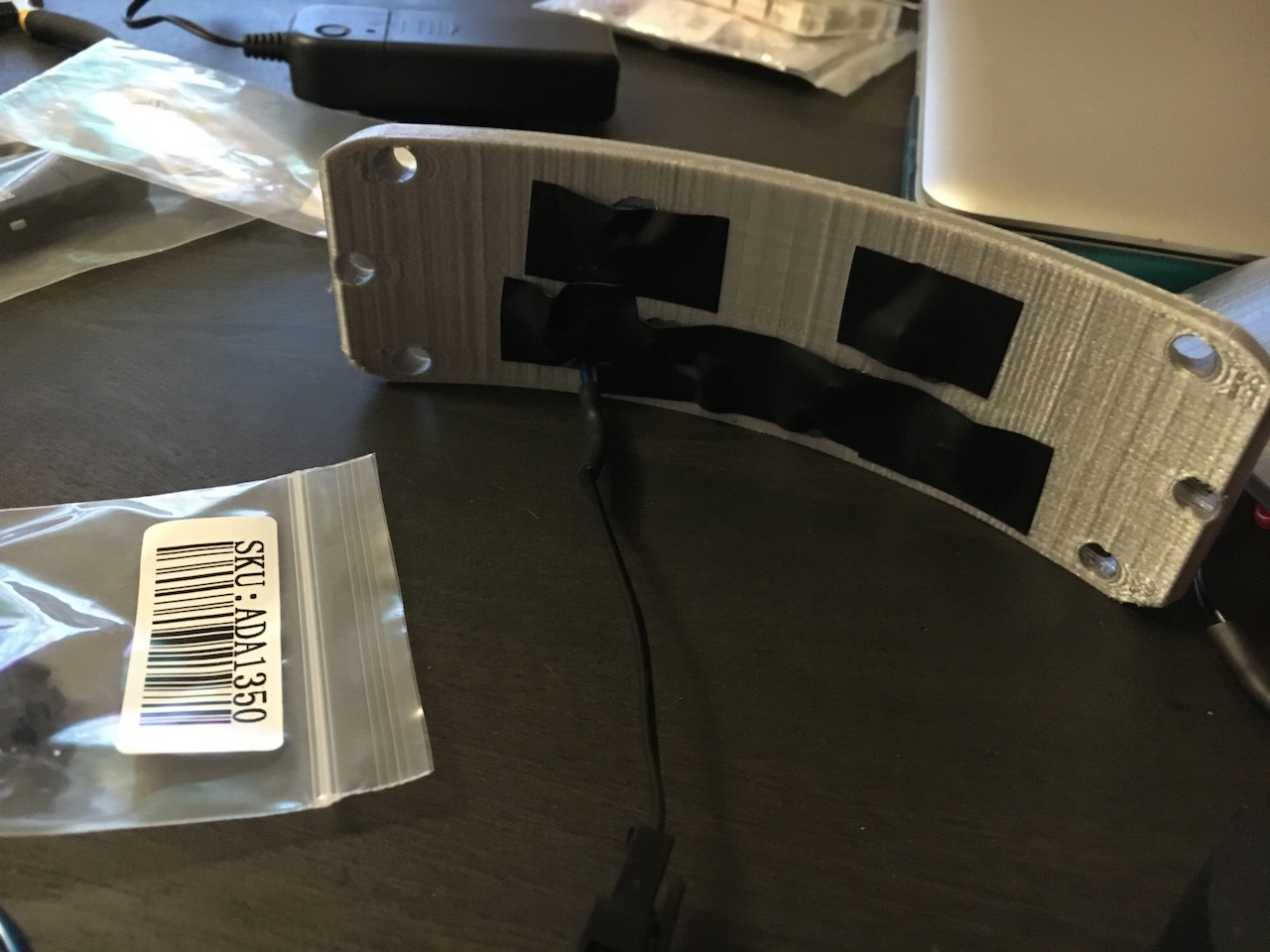
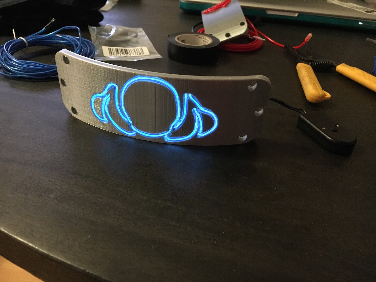
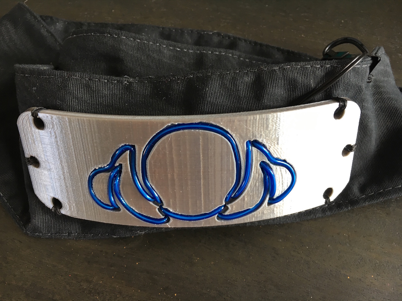
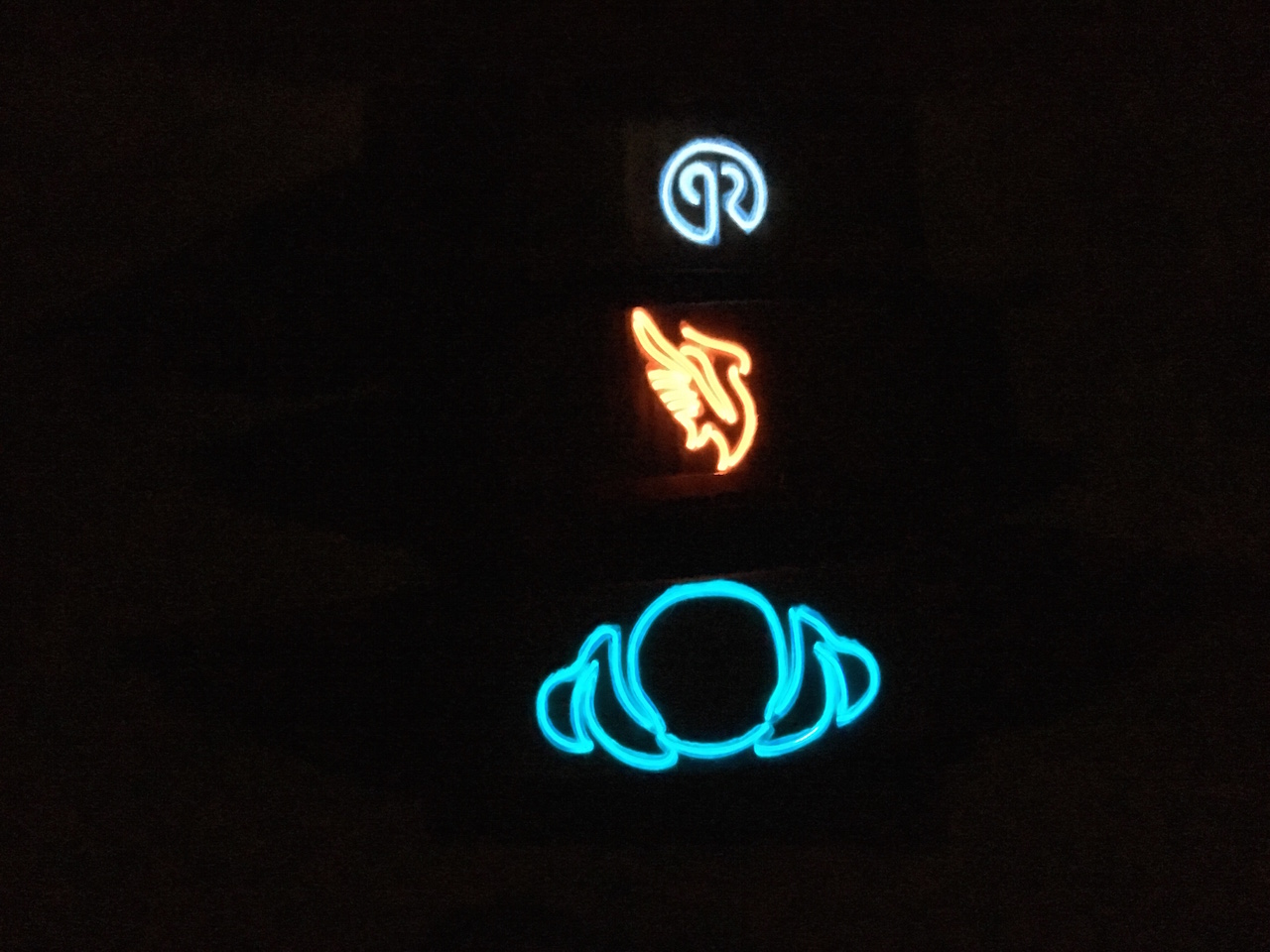
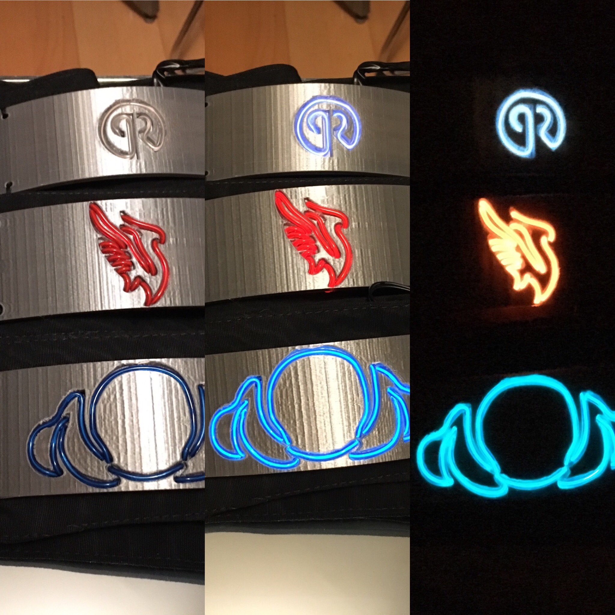
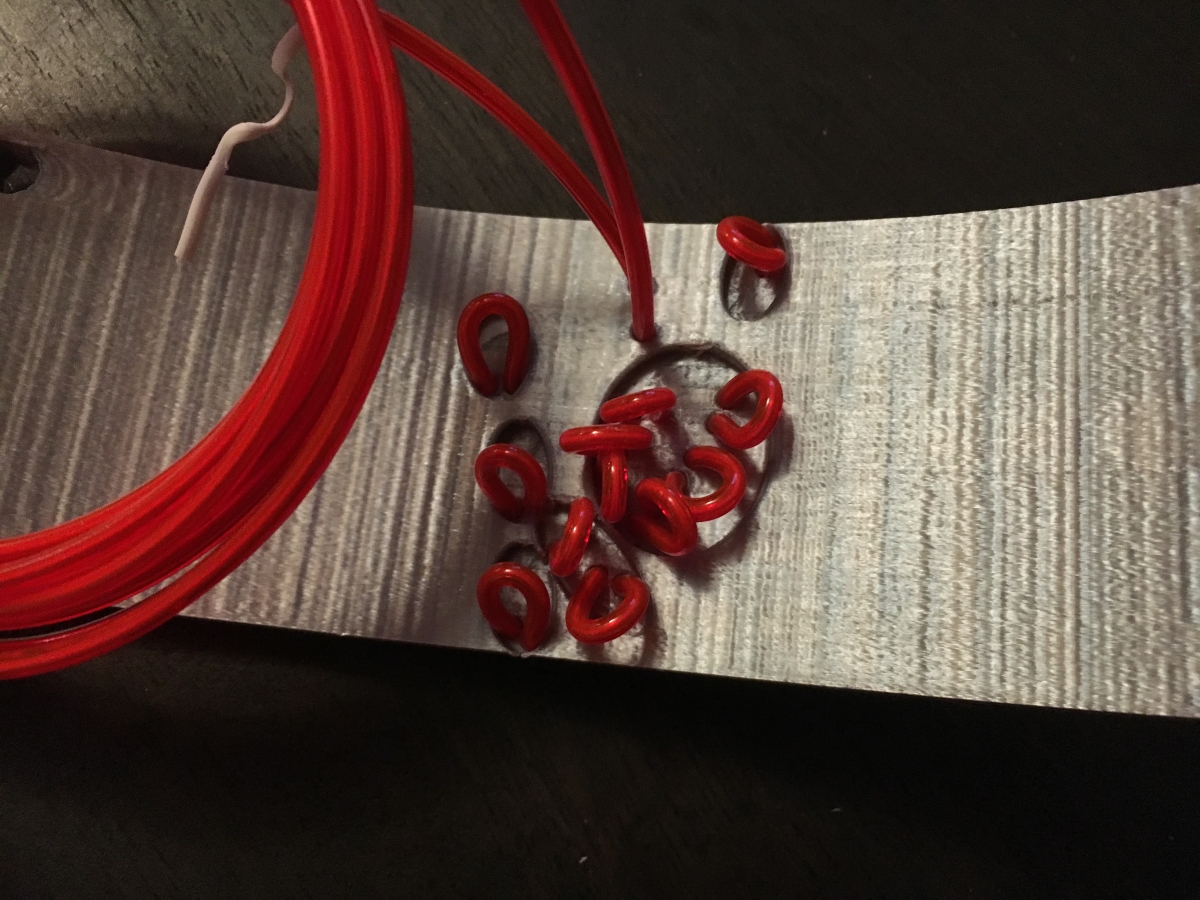
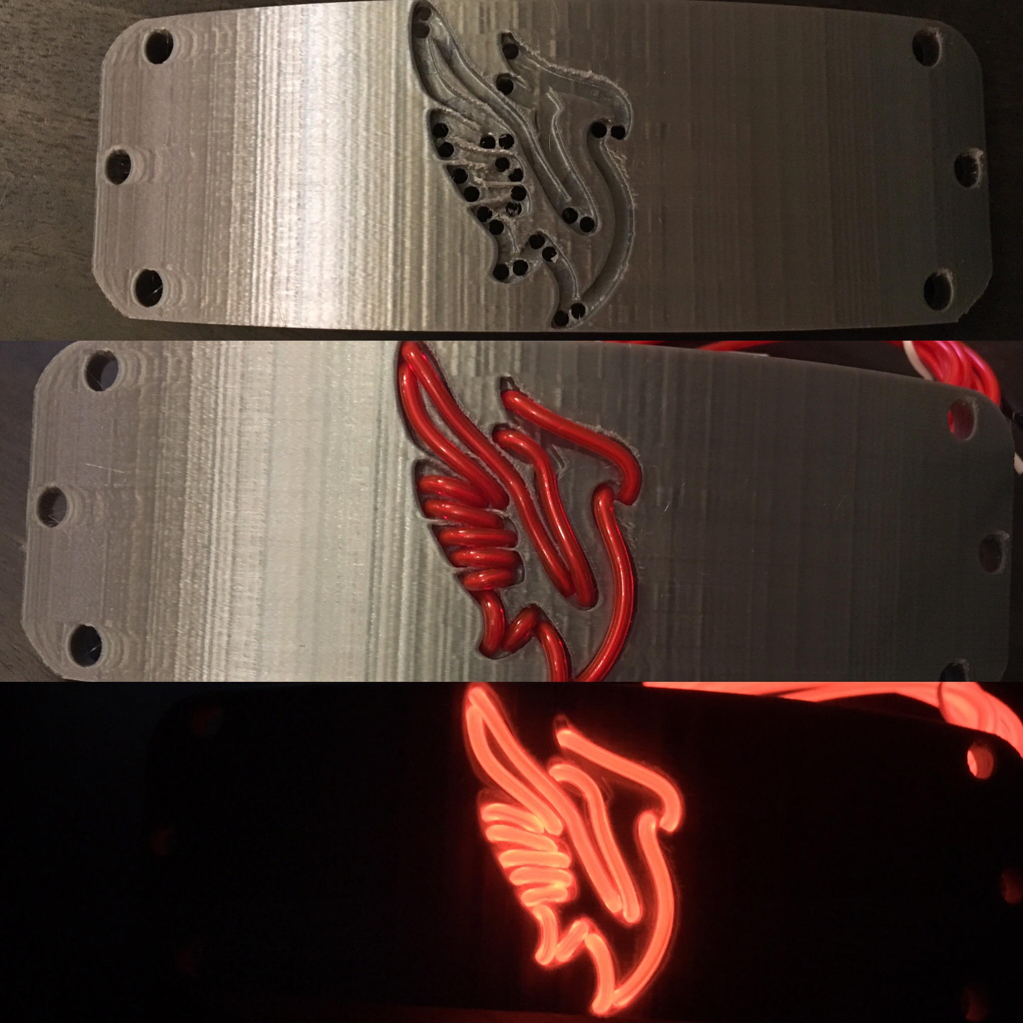
The only thing missing from the completely finished design are a red wire, a yellow wire, and a red led bulb. Anyway, here’s a gallery of my design and build process:

EL Headbands done!

TL;DR: I finished the EL headbands I’ve been working on :D.

I finished up the electroluminescent headbands I described in my post a few weeks ago here. Since my prototype was close to the final product, completing the production was fast after I received the custom fabric components.

As in the prototype, EL wire was passed through the printed channels and connected to a DC to AC inverter for power. I found nifty coin battery sized inverters, which fit directly on the bands without too much interference. The most time consuming portion of the build was attachment of the plastic to the fabric, since I’m bad at hand sewing.

Here’s the build gallery:

Here’s a bonus gif, with a little preview of a flag project I’ve been working on as well…

Thanks Sara and Vi for demo’ing 😀

Supreme EL Box

TL;DR: For my friend Teddy’s birthday, I made him a hypebeast worthy (if I do say so myself) Supreme EL box.

My good friend Teddy is one of the biggest hypebeasts I know, so I wanted to make something he would like. I went back to the EL wire well again for this project (see: headbands https://www.andrewpip.com/2019/03/28/el-wire-lighted-headbands/ and sign <https://www.andrewpip.com/2019/04/07/faux-neon-signage>). However, I needed to dig into my paint supplies dating all the way back to my Iron Man Mask (https://www.andrewpip.com/2018/05/06/infinity-war-masks).

Conceptually, this project was relatively simple:

  1. I made a box.
  2. I cut some channel shaped holes in the box.
  3. I painted the box.
  4. I put my wire through the box.
  5. I gave Teddy the box.

For this project, honestly I think the gallery will explain things better than I can in words, so here it is (it looks nicer if you click to open the full-sized images):

Faux-Neon Signage

TL;DR: For my friend Gina’s birthday, I made her a faux-neon sign to decorate her new condo with. I ended up making a few different versions of this sign and through the process, I learned several useful tricks to speed up vector image modifications, which will definitely make it easier for me going forward. 

I continued playing with el wire since I bought so much for my headband project. Since my friend’s birthday was coming up, I figured it was a great opportunity to make something cool with it. I decided to make a faux-neon sign reading “Mama G’s House”.

I started by searching for neon sign fonts on google and downloaded a few to try out including “Warnes”, “La Patio Script”, “I am online with u”, and “Fenotype Neon”. All of them were free to download, but not all of them were free for commercial usage, which is fine for this project as I’m not selling it.

The first prototype I made used Warnes as the base font. I really liked how the letters all connect at the bottom. However, I needed to do a bit of surgery in Inkscape to connect the disparate words after vectorization:

The main modifications I made to this first font were just around connecting the letters and adjusting some of the spacing

I imported the SVG directly into a sketch Fusion 360 and resized it to ensure I had a ~3mm wide channel all over. Next, I modified the sketch to remove areas near the bottom where the lettering overlapped. In a fashion similar to what I did for the EL headbands, I extruded a positive model of the letters. Next, I needed to move the apostrophe body and combine it with the rest of the lettering. Then, I created a sketch, offset the entire object, and cleaned up the line overlapping lines created by the offset tool. After extruding the outlined body, I cut the positive lettering model out:

I reused the technique I discovered while making the EL headbands of cutting the positive channel from the main body

After slicing the STL in Cura, and waiting about 3 hours for production, the print came out pretty well:

However, with the physical model in front of me, I saw the font I used had a few issues. Primarily, although the channels I made fit the el wire, there were too many places where stringing it required a double back, which was not accounted for. Oops. Luckily, I hadn’t spent a lot of time on this, and I figured Gina could still use it as a nice decoration even without lighting effects.

The next font I tried was called “I am online with u” which had the advantage of being a single connected line. Although this font was more ideal out of the box, I still needed to tweak the vector version to make it work properly. Essentially, I just modified the “corners” of the letters to allow for more space wherever they changed direction, I adjusted the spacing between words and letters, and I moved and combined the apostrophe to overlap with the letters.

I modified this font a bit more heavily to ensure a good print. The biggest tweak was widening the letters where they changed direction so the EL wire could bend around.

My workflow in Fusion 360 was essentially identical to the one I used for the previous version of the sign: import svg, scale, and clean up sketch -> extrude a positive channel -> offset the body and extrude the outline -> use the combine tool to cut the positive channel away from the outlined body. Unfortunately, this part was a bit too big to fit on my printer in one piece, so I needed to split it into two. The split created a physical weakness which I shored up by creating a small base to hold it together and help the entire assembly stand upright.

The split was unfortunate but necessary to allow me to actually manufacture the sign. The base I made fit very well and helps keep the assembly standing too.

The print didn’t take very long—maybe about 4 hours in total for all the pieces. I was pretty happy with the results, and I think she was too 🙂

El Wire Lighted Headbands

TL;DR: My friends asked me to make custom light up costume headbands for them in the style of Naruto… so I did. I 3D printed channels through which I fed electroluminescent wire to make logos of their favorite DJ’s. While the project is simple in concept, I needed to dust off a bunch of tools I hadn’t utilized in a while to complete it. While I’m not quite finished with these, I’m too excited about how the project is looking NOT to share.

In the anime Naruto, the characters wear headbands to protect their foreheads while they fight. My friends wanted ones that light up for their costumes, and asked if I could help. If you want to skip over a lot of unnecessary detail, just go to the gallery at the bottom where I put the build photos 😛

El wire is a fantastic way to add lighting effects to projects since it is very bendable, easy to install, and does not require any programming at all (just add power!). Before this project, I hadn’t played with electroluminescent (el) wire for years, so I was excited to jump back in. The technology has become a lot more common and widely available than I remember—there’re tons of vendors for wire and the requisite DC to AC inverters. Unfortunately, the inverters still make an annoying high pitched buzz whenever they’re on.

In terms of the mechanical design, the headband was very simple. I created a base in Fusion 360 CAD to reuse in each version with a different logo. The majority of my time has actually been spent optimizing the image preparation pipeline. To go from a 2D-logo to a cut channel, the process I went through was as follows:

  • Prepare an outline image in Gimp (a free Photoshop competitor). The easiest way I found to do this was by using the fuzzy select tool to select the outline of the image I wanted to convert, then using the stroke selection tool.
Using stroke was key to getting a nice solid outline to begin my vector image with
  • After saving the image as a bitmap in Gimp, I imported the file in Inkscape (similar to Adobe Illustrator) and stroked the bitmap to a path. I resized the vector image to fit my headband base, and manually edited the nodes until all parts of the path were approximately 2.5mm in width to fit my el wire.
I ended up doing quite a bit of manual manipulation to change the logo shape such that the 2.5mm channels would fit and still look somewhat like what I started with. Simple automatic offsetting didn’t work well at all.
  • Initially, I was exporting vector images as 2D CAD-friendly DXF files. However, I made the groundbreaking discovery that Fusion 360 actually lets you directly import and use SVG files. Using the vector files (svg) directly is a lot more computationally friendly and MUCH easier to work with. For example, the dxf version of the Illenium logo had upwards of 670 line elements, whereas the svg file had two curves.
I can’t believe it took me so long to realize I could use SVG’s directly in Fusion 360… this was a gamechanger for my speed of productivity.
  • Within Fusion 360, I directly extruded the imported drawing. Next, I did a few manipulations with the combine and move bodies menu to create a “positive” model of the channel I wanted to CUT from the headband.
It’s a bit difficult to see, but I moved the positive cut out forward so it only intersects the model for the last 2.5mm of its extruded depth.
  • One of the limitations of working with el wire is that there is a minimum bend radius before you can actually break the wire and cause shorts. Unfortunately, since I was making headbands most of the detailed bends weren’t physically possible to make in a single piece. To maintain sharp edges required for the logo designs, I created pass through holes. This allows me to bend the wire in an unsightly loop where it can’t be seen in the final product. Positive models of the pass through holes were created by extruding cylinders from behind the headband up to the channel model.
Thru holes were simple extruded cylinders
  • Lastly, I created some “channels” on the back of the headbands to accommodate the loops. In an early prototype, I created actual channels out of spline sketches, but that proved to be a lot of work for no reason. Now, I’ve simply created large inset areas that can fit the el wire loops. It’s much less effort to achieve the same result. The positives for this were extruded initially as separate bodies to the channels so I could shift them backward about 0.8mm before joining to the rest of the positive channel model.
I cut the positive channel model away from the base headband shape
  • A simple combine, export as STL, and slicing in Cura resulted in a pretty decent print, if I do say so myself ;).
Here’s my first prototype blinking 😀

The first prototype I printed was in black PLA before I received this gorgeous silk silver shiny PLA made by Hatchbox on Amazon. I quickly realized that I didn’t have a great way of making the fabric for the bands since I don’t have any sewing skills. I am incredibly lucky to have super talented parents (check out my dad’s website here… he’s much more artistically talented than I am: www.bounsaypipathsouk.com) who are always willing to help. I Facetime called them to explain what I was making and mailed them my first sample. A few days later, I received some photos of my prototype solidly attached to a custom headband they made, and should receive them next week :D.

My parents were able to deliver!!

While there are still a few improvements left for me to make before I deliver my final product, I’m pretty stoked at how well the project has turned out so far, and just couldn’t wait to share.

As promised, here’s a gallery of the build: