TL;DR: I uploaded my first Thingiverse share! I improved the design of an
existing Ironman model by adding pegs to allow for articulation and adhesive-less
assembly.
I went on a work trip to Phoenix in early November. Fortuitously, my best
friend growing up lives there and loves Ironman like I do. I decided to squeeze
in a quick design and print project to gift him.
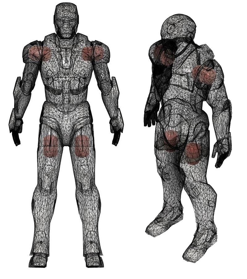
I found a decent looking Ironman figurine on Thingiverse here. This model is actually a remix of another project—the remixer made the part easier to print by separating the limbs. While this was a good step forward for printability, I further improved the design by adding pegs between the extremities and the main body:
The pegs I added are in red. They allow easy assembly plus articulation.
The boolean tools available in Fusion360 make it incredibly easy to complete
simple changes like this. I undersized the peg in the CAD model, but small variations
in print settings and nozzle wear and tear make perfect fits a bit tricky. In
fact, it took me a few tries to get the pegs working really well, but the
prints were short, and the results were worth it:
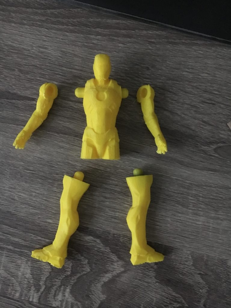
Assembly in process
Given that this project originated directly on thingiverse, I thought it was only right to give back to the community and share my very first remix here: https://www.thingiverse.com/thing:3998580. The number of views and downloads of this model pleasantly surprised me, given the simple and obvious nature of the change I made. I’ll probably consider sharing more stuff going forward… we’ll see ¯\_(ツ)_/¯.
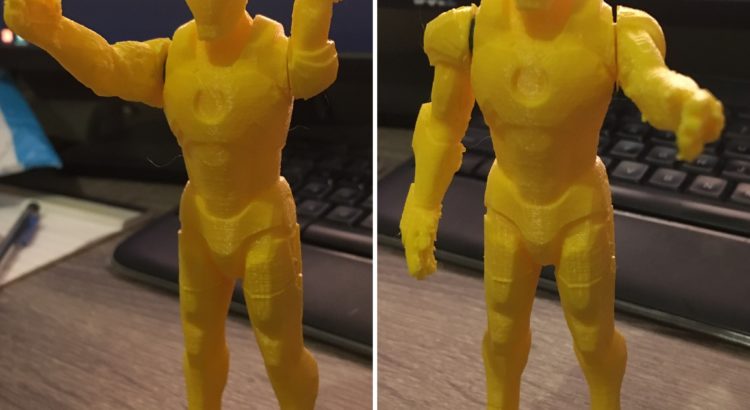
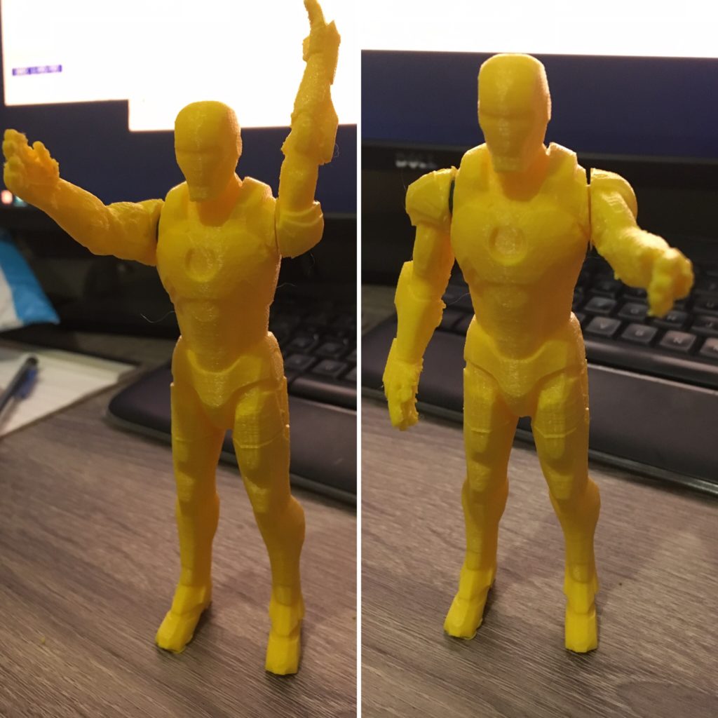
I think the assembly with articulation turned out pretty well—the yellow
looks vaguely gold-ish, so the only thing missing is some red paint:
TL;DR: I made a villainous dice tower for a friend’s bday, combining two of
his favorite things—Star Wars and board gaming.
October was a pretty busy month for me with work and fantasy football both
ramping up. However, I’m very happy I was able to get some design and project
time in. My friend Nick’s birthday was earlier this week, and I wanted to make
him something practical yet personalized. Anybody who knows him at all knows
how much he loves both board games and Star Wars, so to me, printing a Darth
Vader dice tower was simply a no brainer.
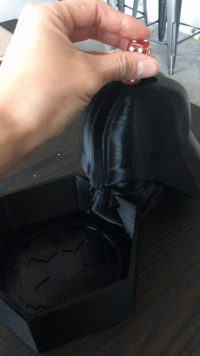
For those of you who may not know, a dice tower is a very simple device to ensure
fair rolls while keeping dice from flying all over the place and messing up
stuff on the table. Dice towers can take on a wide variety of shapes and sizes.
All that is really needed is some sort of aperture at the top to put dice in, a
path which randomizes spins, and a tray to collect them at the end.
Before I started designing, I did a quick search on thingiverse and other 3d
print sharing sites to make sure I wasn’t completely reinventing the wheel. I
found a few Vader dice towers, but to be honest, I didn’t think they were very
good in terms of amount of detail and general aesthetics. I was fortunate to find
a great model of Darth Vader to begin with: https://www.myminifactory.com/object/3d-print-star-wars-darth-vader-30-cm-tall-60500.
Essentially my plan was as follows:
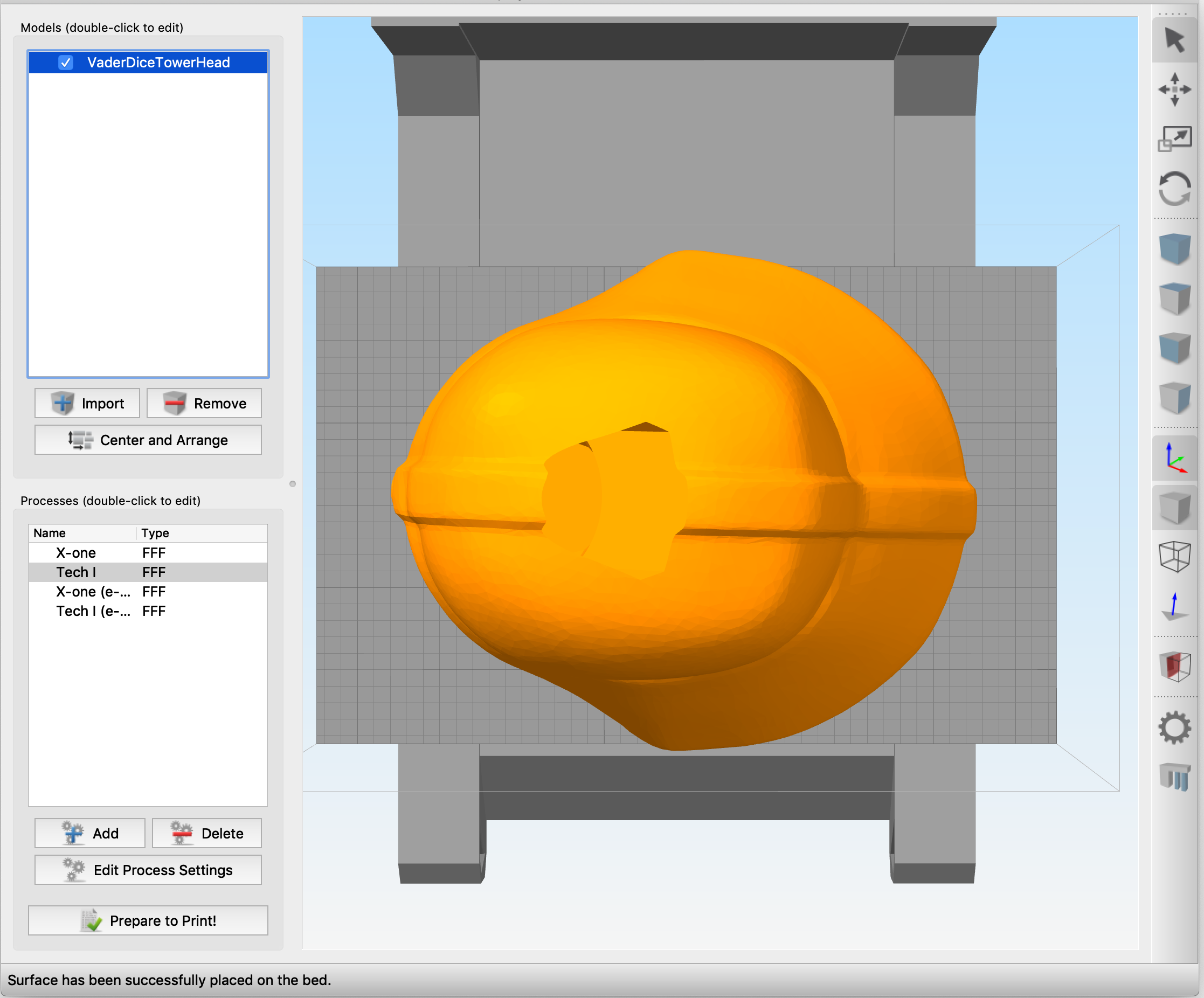
Reorient and resize the head to maximize the print area
on my bed.
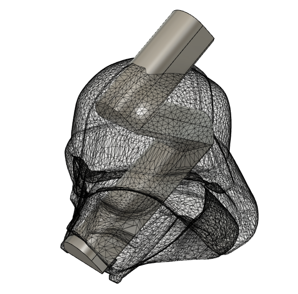
Create the dice travel path leading from the top of the
head out of the mouth.
Subtract the path model from the head model.
Create a tray to catch the dice
Print the parts
Ship it
Parts 1-4 went incredibly smoothly all within Fusion 360. I successfully
printed a ¼ size test part to ensure the path I created could be printed
without any internal support structures to minimize post processing work.
Unfortunately, I then ran into printer issues I had never previously
encountered…
My Monoprice Maker Select Plus (aka Wanhao Duplicator III Plus clone) has
been a workhorse without any major issues for years now. Of course, she decided
to act up when I was up against a deadline since birth dates are immutable. My
printer would randomly stop working and send bed temperature errors before
rebooting. I pinpointed the problem to the thermistor on my print bed, but I
didn’t have time to mess around. Luckily for me, my neighbor across the street
literally has a print farm in his bedroom (15 machines and counting) so I was
still able to get the parts made on time. The only unfortunate thing is that
his machines are smaller than mine—so he had to scale the size down by 5% to
get them to fit. (I found out later that the fix I needed on my printer was
incredibly basic: the kapton tape holding the thermistor to the bed loosened
over time, thus the printer received intermittent temperature readings.)
Luckily, the 5% reduction in size did not severely diminish the part’s
functionality:
It works! May the Force Be With You!
I’m incredibly happy with the results of this project. I enjoyed the challenge of modifying an existing mesh to create a new, meaningful, and practical object. Even though UPS spoiled the surprise by giving Nick a notification about the arrival of a package sent from my area, and the package arrived late, I’m pretty sure he was very pleased upon arrival.
Thanks for making it to the end of this post—here’s an incredibly sparse
build gallery:
Editing the existing mesh was an interesting challenge. I wanted to make the exit orifice blend in with the head as much as possible while keeping the design printable without internal support structures.
My awesome neighbor was able to help me get the parts printed--unfortunately his print bed is different from mine, so he had to scale it down by 5% to get the head to fit.
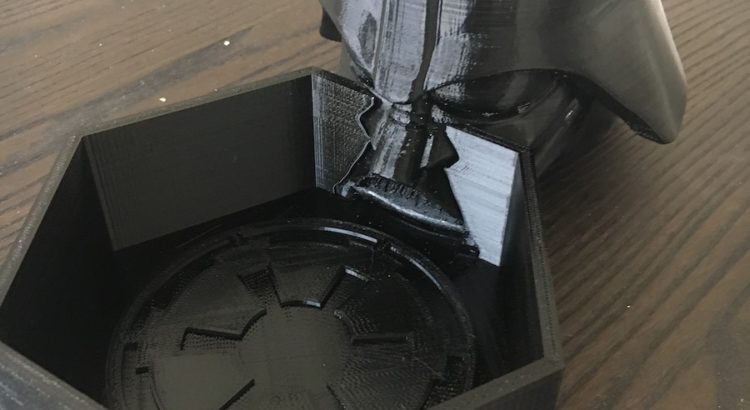
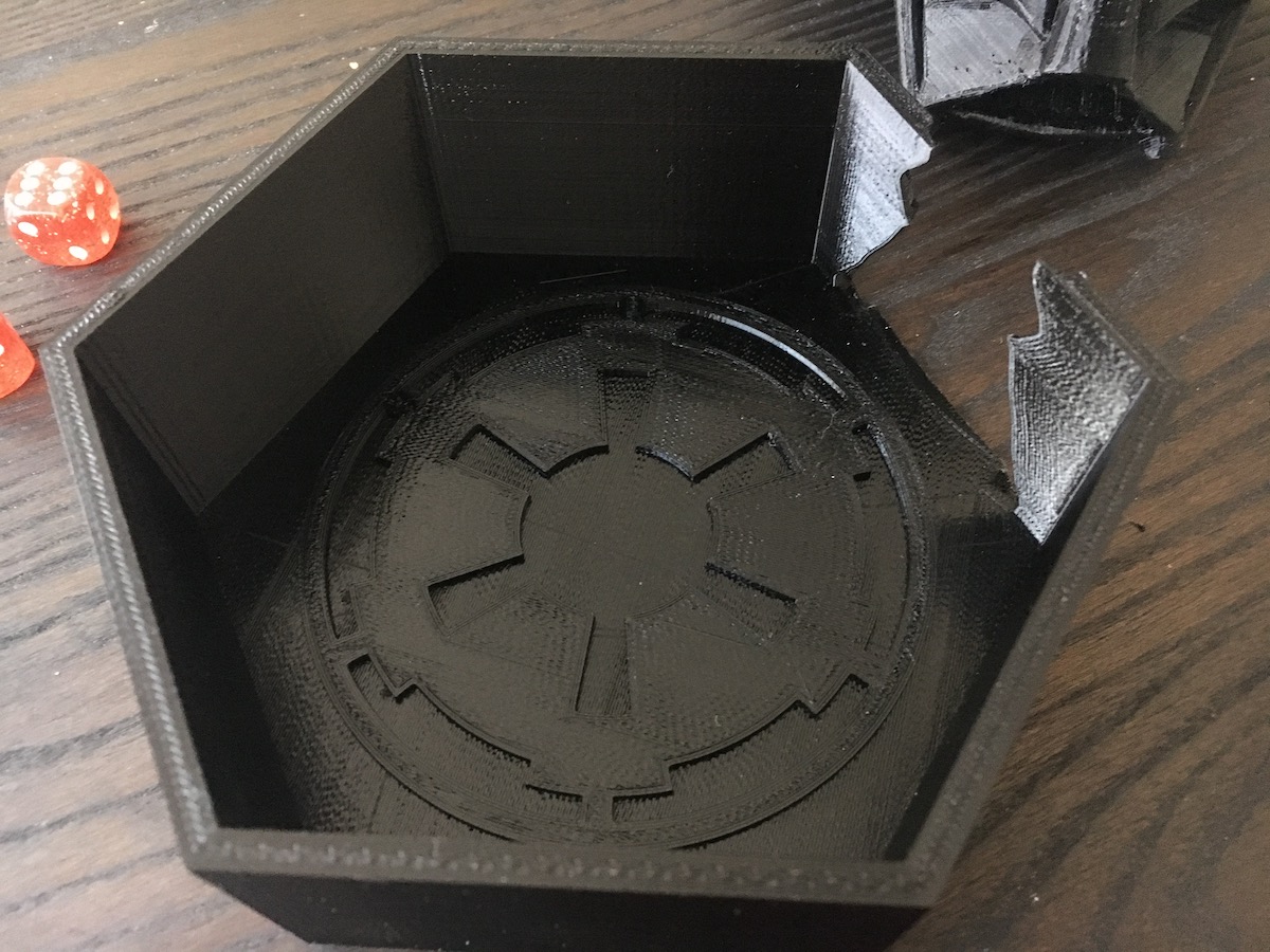
Dice tray with the emblem of the First Galactic Empire.
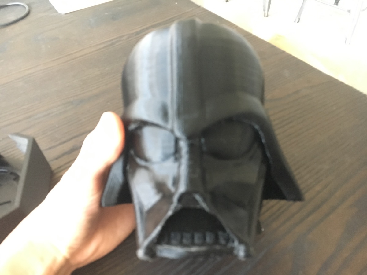
Apologies for the blurriness of this photo. It's Vader's face with a cutout for the nose/mouth filter.
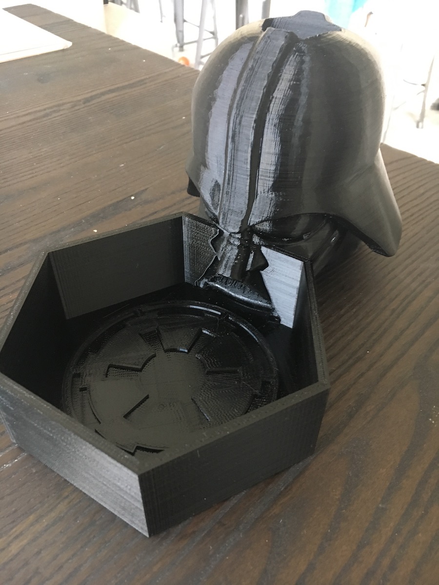
Here's the completed project--head and tray together.
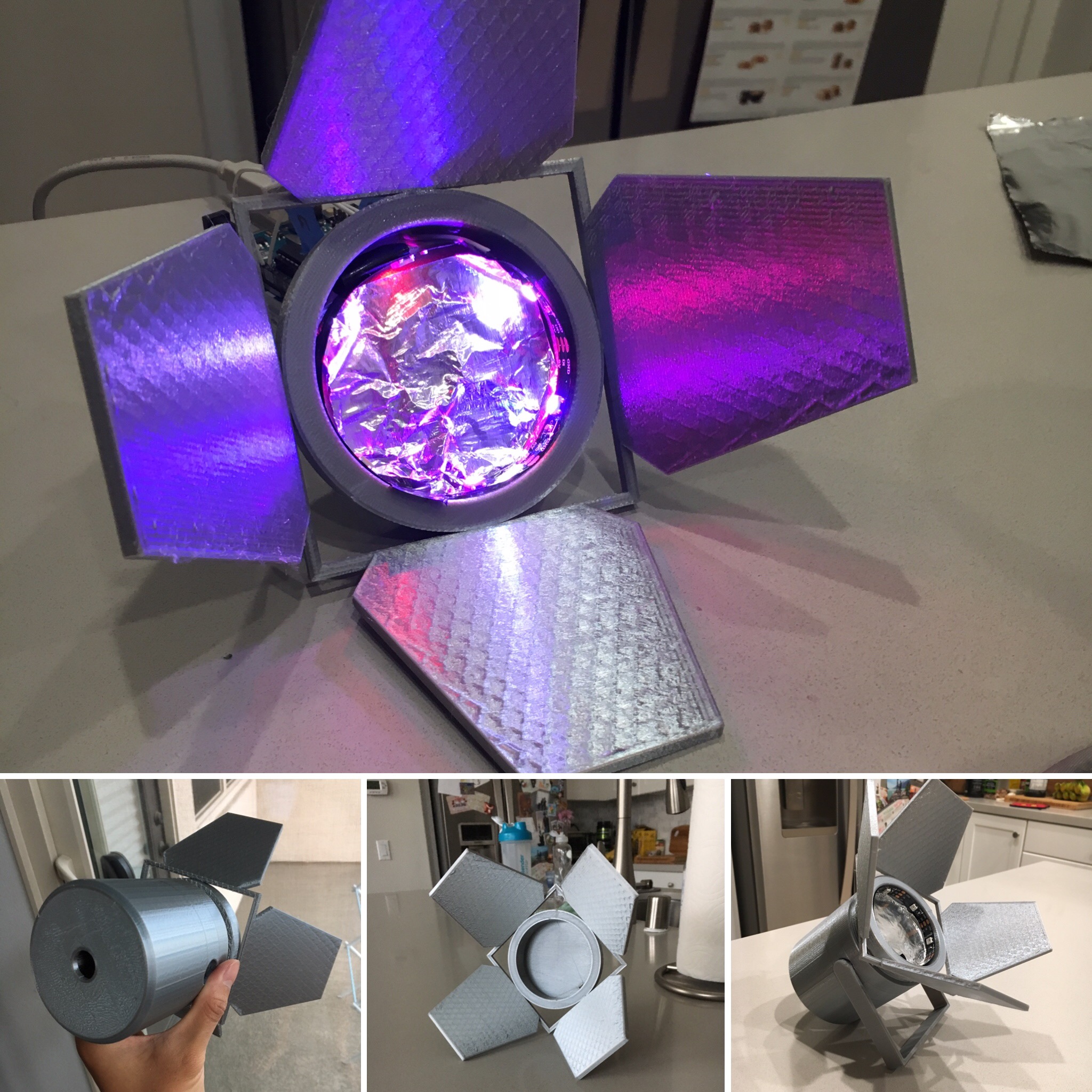
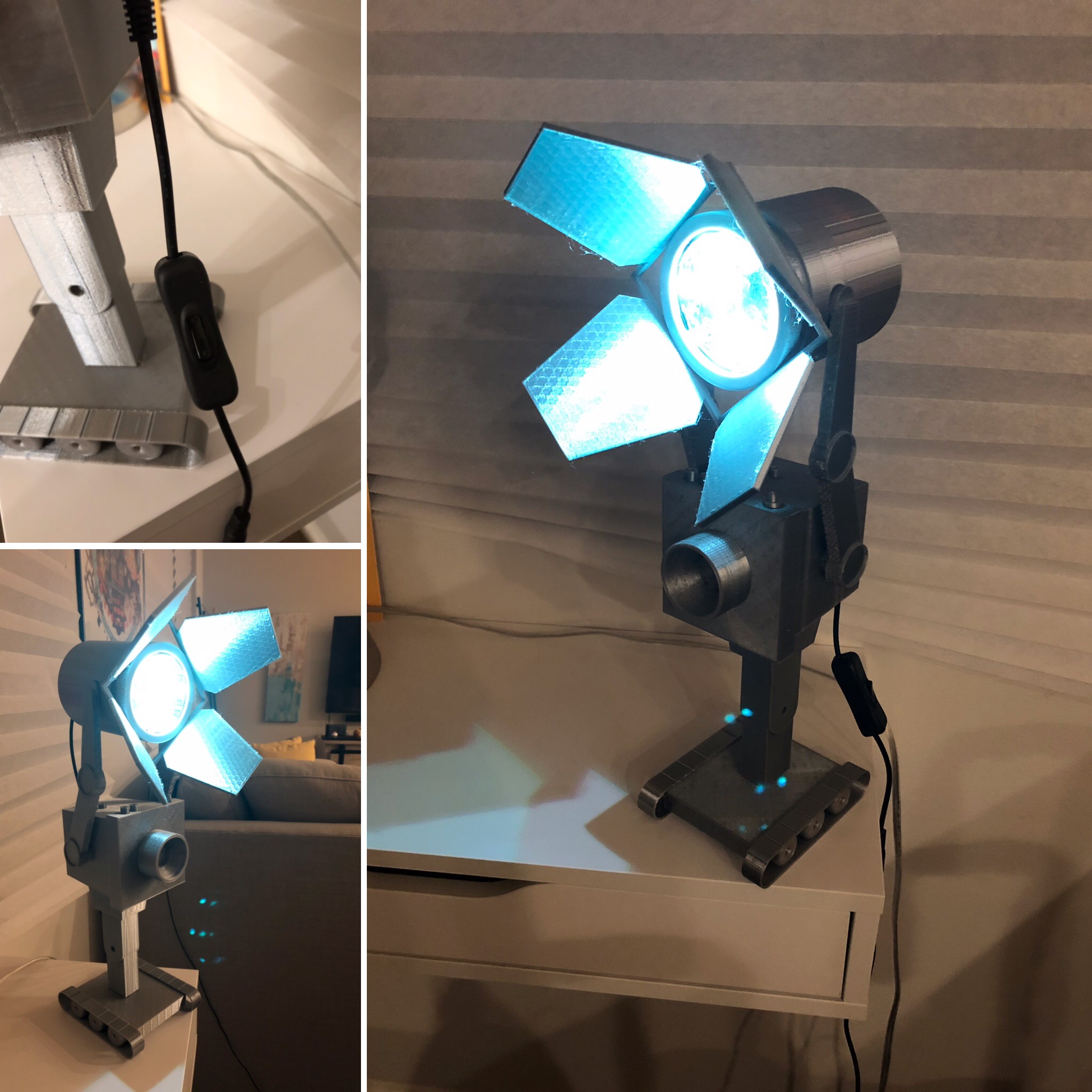
TL;DR: I made a robot whose only purpose is to hold up a spotlight… At
least it’s a step up from passing butter :D. I am extremely pleased with how
this guy turned out. The light is adjustable both in leaf rotation and tilt
angle.
A few weeks ago, I desperately wanted a lamp for my nightstand to keep me
from needing to stumble around in the dark trying to find the bed while
avoiding squishing the dog after turning off the lights at night. Thus, I
decided to do the most practical thing, and began designing my own.
I began my design around the idea of creating something in a modular manner.
I knew I wanted to have some sort of character holding up the light source, but
was unsure about the specifics of what was going to be feasible, and what would
be accepted by my landlord to have around the house. I landed on the idea of
building around a spotlight—I like the simple shape and general aesthetics and
the character-neutral nature.
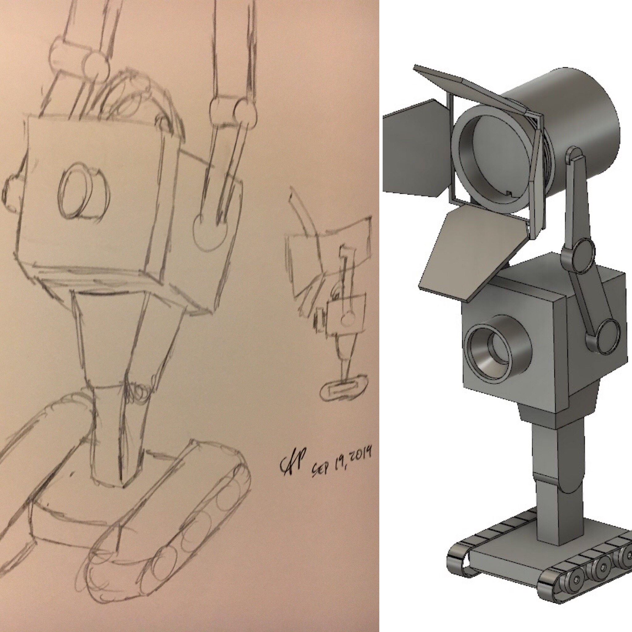
Over the next few weekends, I kicked around a few ideas and asked some
friends for inspiration when I had my eureka moment—THE BUTTER BOT FROM RICK
AND MORTY IS PERFECT FOR THIS!!! I am a huge fan of the show, wanted to use up
my silk silver plastic filament, and thought I could give this little guy a
better purpose than just passing butter. Really, it was a win/win/win scenario.
I don’t have any photos detailing the electronics, but I’ve got a simple ATmega32U4-based
Arduino board with a micro-USB interface. I found this awesome inline DC jack
power switch and paired it with an even cooler DC jack to micro-USB cable to
provide power and add the ability to turn the light on/off.
Designing and implementing my idea was relatively straightforward after
deciding what to build. The trickiest part was designing the parts in such a
way so they could be broken up and printed in different jobs—the overall size
is roughly 7” x 8” x 18” (although the 7” width can change depending on how the
spotlight leaves are oriented, and the height can change depending on the tilt
angle). I am particularly proud of my insight of creating a domed peg to enable
the printing of the main body without the need for supports.
The only thing missing from the completely finished design are a red wire, a yellow wire, and a red led bulb. Anyway, here’s a gallery of my design and build process:
I started off by building a simple spotlight. I took care to add mounting features and access holes for the electronics. I probably could have added more shell layers to prevent the supports from being visible in the leaves, but it's not too bad. I added a piece of aluminum foil at the bottom of the spotlight for a bit more reflectivity.
I love sketching. I still find it the fastest way to get ideas out of my head, and somewhat into the real world.
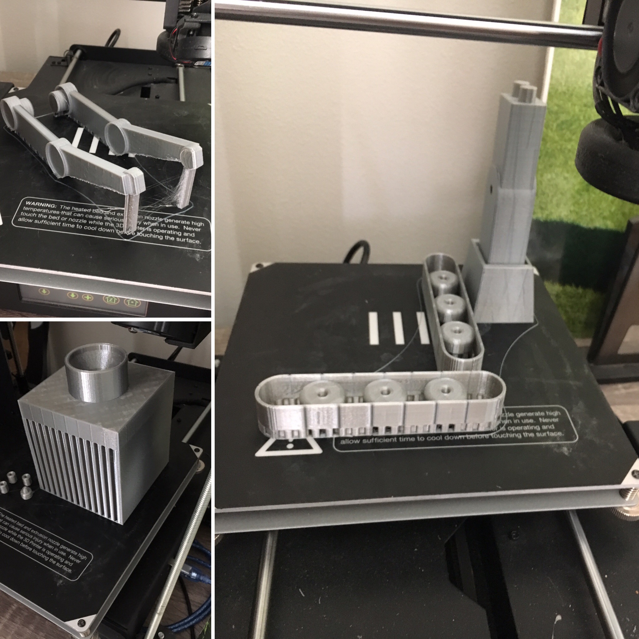
Since this project is relatively large, I needed to break the printing up into several print jobs. The spotlight itself was printed in two parts--main body and leaves (8.5 hrs, 14 hrs). The ButterBot was broken up into prints consisting of the base (not pictured, 4 hrs), arms (6 hrs), main body + treads (10.5 hrs), and head (18 hrs), for a grand total of 61 hours of print time and roughly 400 grams (almost half a roll) of filament.
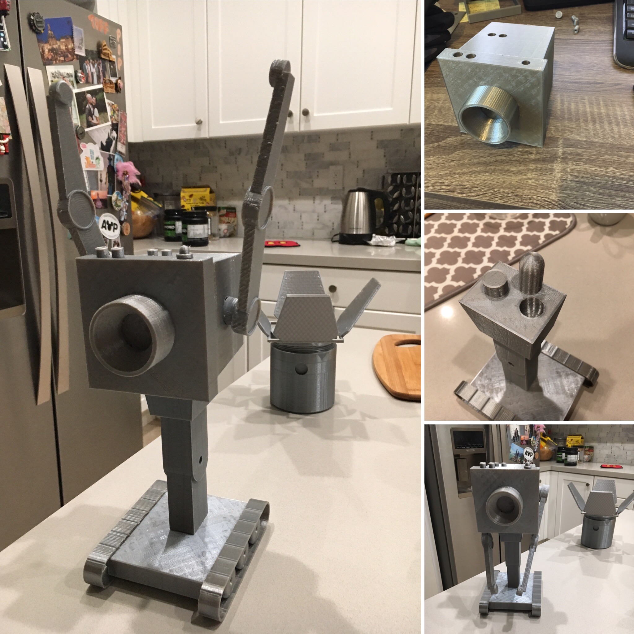
Assembly was pretty straightforward since I took care to design everything to fit together well. The arm positions are slightly adjustable and the tilt and rotation of the spotlight leaves can be adjusted as well. I am particularly happy about making domed pegs and holes (upper right) to prevent the need for supports.
The inline DC power jack and DC to micro-USB cable are a lifesaver and are huge in adding easy functionality. They're probably the coolest component finds for this project.
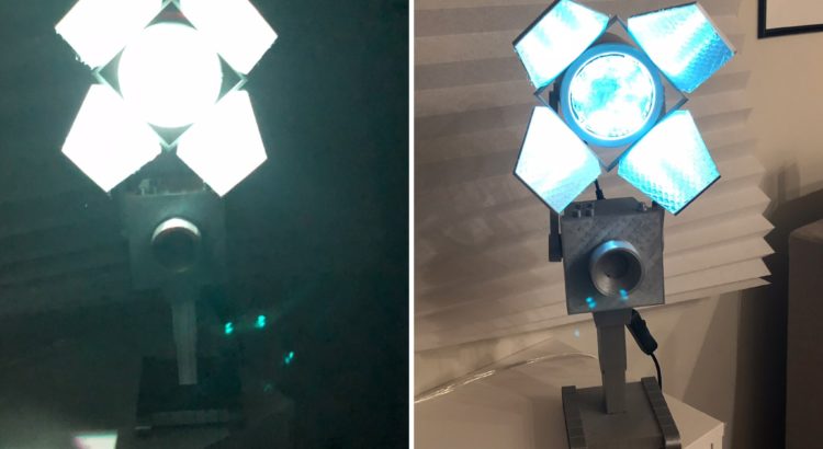
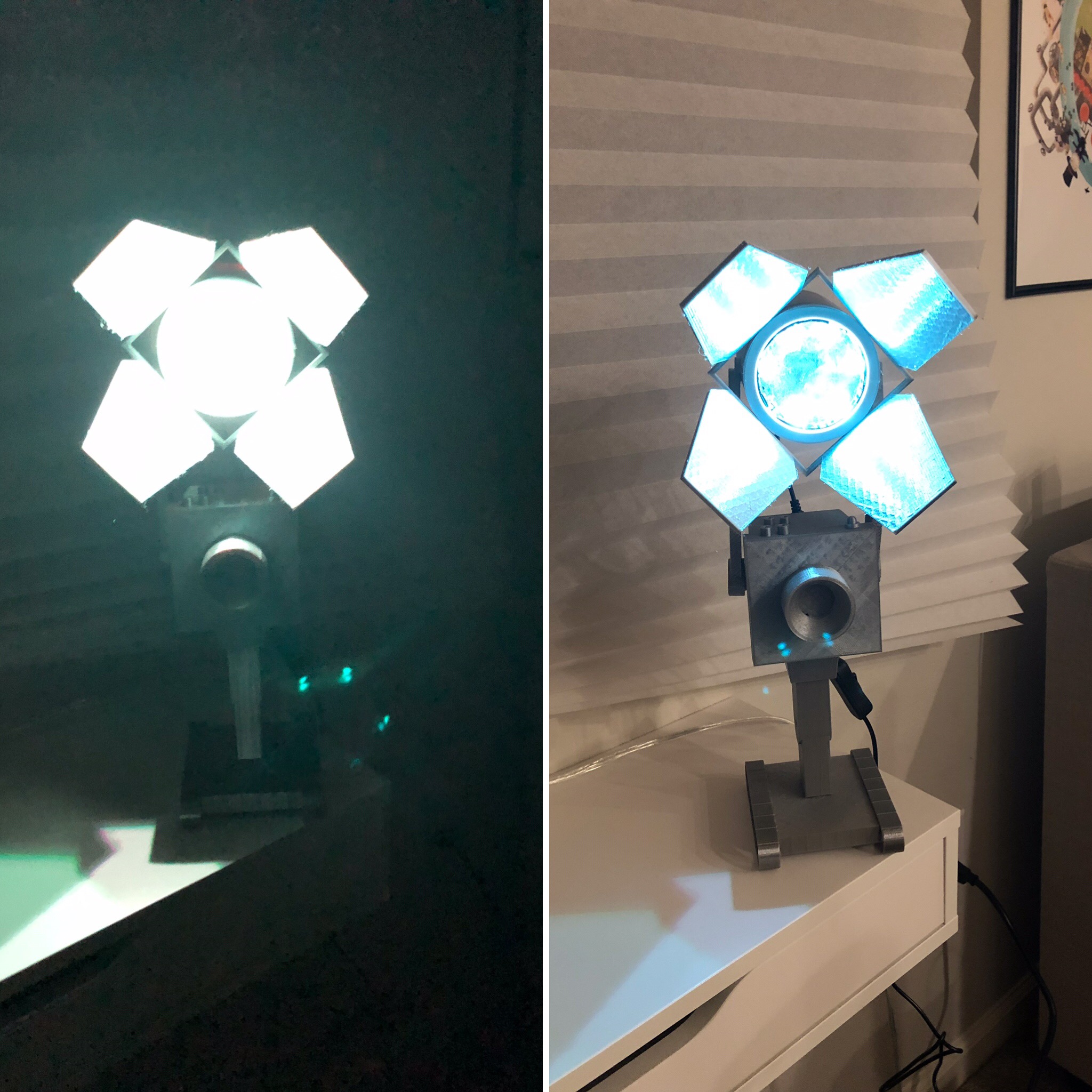
A lights on/off comparison. Sorry I don't have an iPhone 11 pro yet, so my low light shot is whack. I'm actually pretty pleased with how reflective the spotlight leaves are.
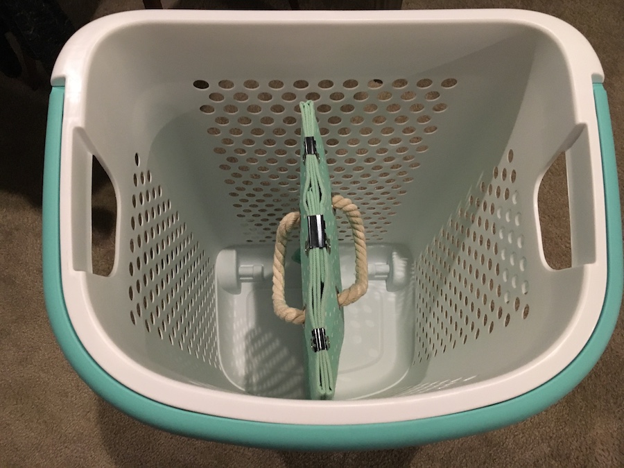
TL;DR: I made a divider for our new laundry bin using material from our old
bin and printing some threaded pins to hold it in place.
We used to have a stiff cloth laundry basket, but there were two main
problems with it. Whenever I tossed my clothes on it inaccurately (this
happened all the time, let’s be real), the walls would buckle a bit under the
weight. Secondly, there’s just a single compartment, and I’m allergic to the
laundry detergent Tiff likes to use.
To fix the first problem, we actually used the ubiquitous 20% off Bed Bath
and Beyond and bought a new hard plastic hamper. To address the second, I got a
bit more creative. Since our old laundry basket was cloth-based, I was able to
fold it up using binder clips. The divider fit very tightly near the bottom, so
I only needed a way to hold it in place closer to the top. I created a pocket
on each side by adding two binder clips around where I wanted to place the
holder.
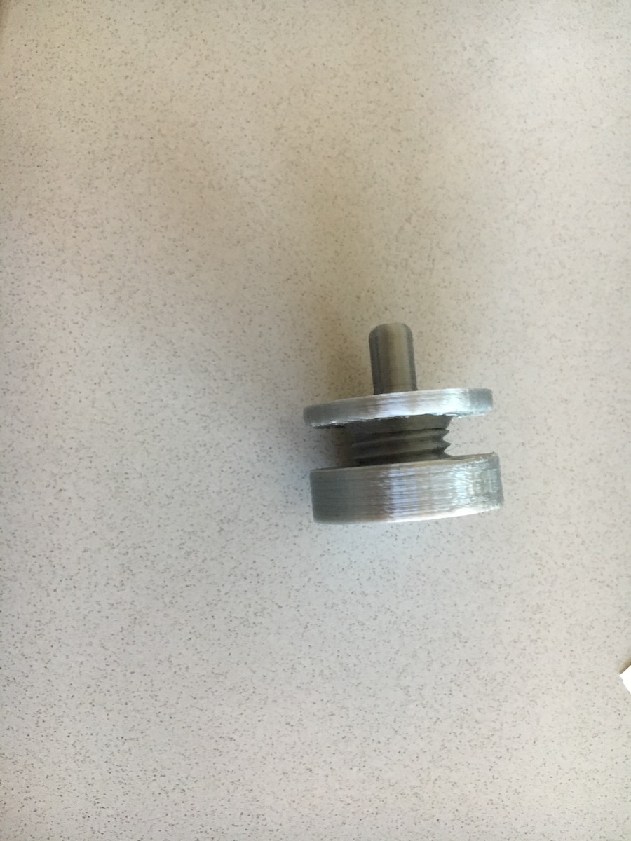
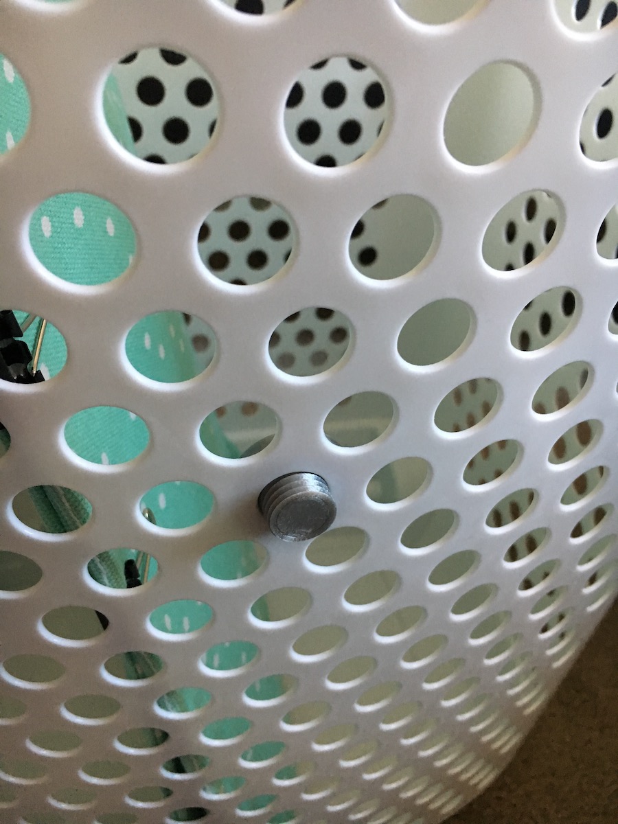
The custom design I went with was very simple—it’s a simple threaded pin and
retaining nut. I measured the hole I needed to fill, extruded a few cylinders,
and added threads, ezpz. About two hours on the printer later, I installed two
pins with nuts on the basket and put the divider into place.
I’ll be the first to admit that this isn’t my sexiest design ever, but it’s
quite utilitarian.
Here’s a few build photos:
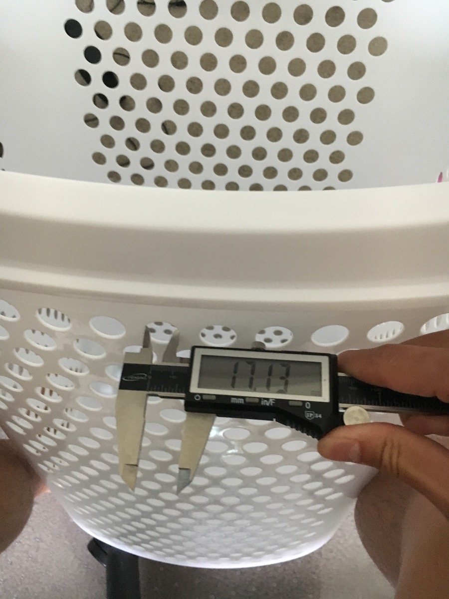
The first step was to measure the size of the holes I needed to fill.
I was very happy that the threads were large enough such that they worked well on my printer without any issues.
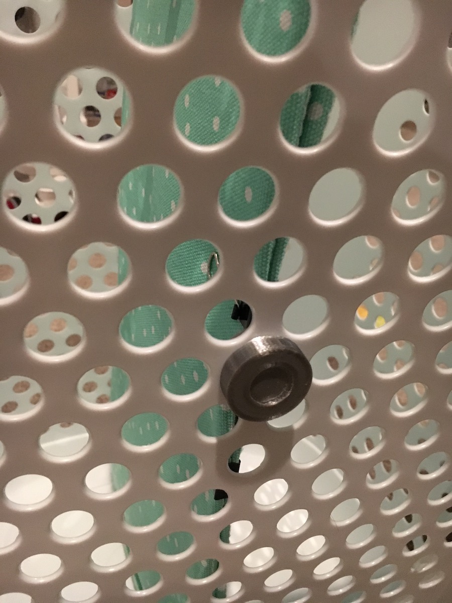
Part 1 of the installation--adding the thread through the hole
Part 2 of the installation--fitting the divider onto the pin head and tightening the nut.
Here's a top view of the basket with divider installed. As a bonus, the color schemes matched pretty well 🙂
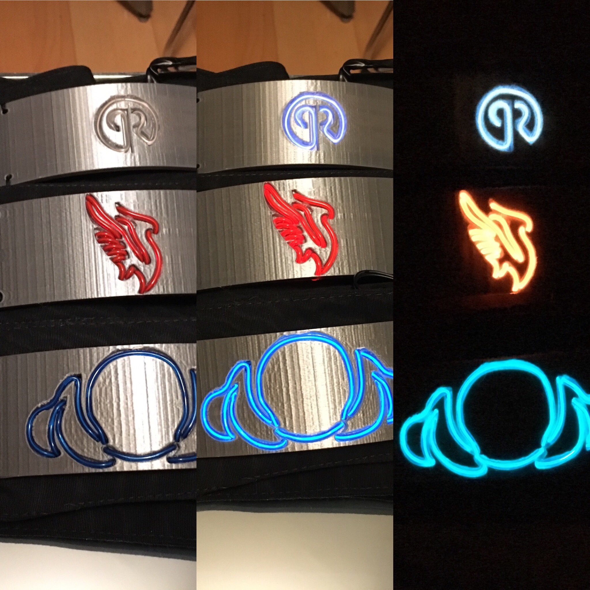
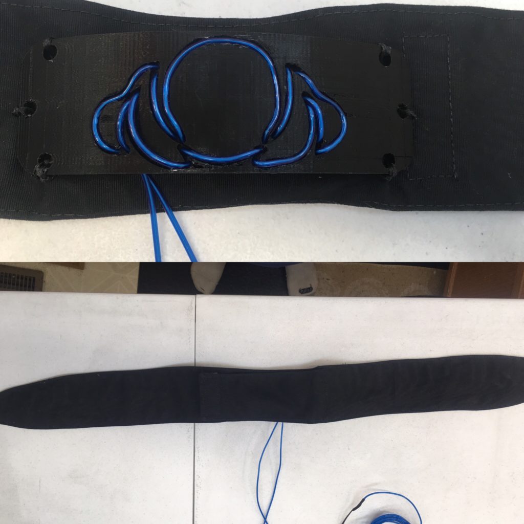
TL;DR: I finished the EL headbands I’ve been working on :D.
I finished up the electroluminescent headbands I described in my post a few weeks ago here. Since my prototype was close to the final product, completing the production was fast after I received the custom fabric components.
As in the prototype, EL wire was passed through the printed channels and
connected to a DC to AC inverter for power. I found nifty coin battery sized
inverters, which fit directly on the bands without too much interference. The
most time consuming portion of the build was attachment of the plastic to the
fabric, since I’m bad at hand sewing.
Here’s the build gallery:
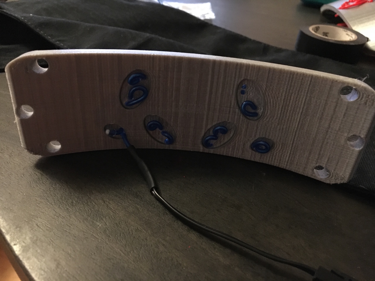
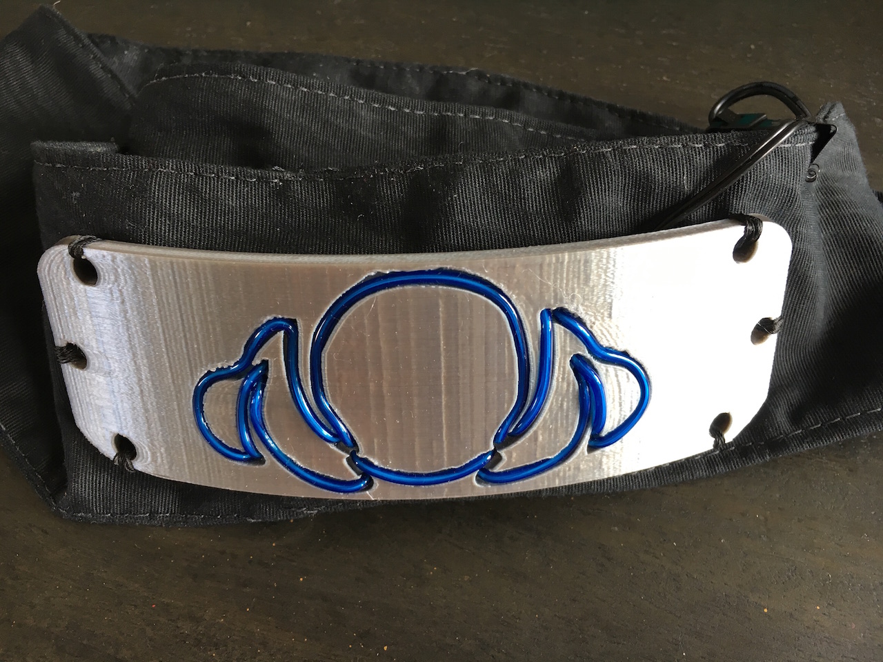
The pass thru holes and cutouts to accommodate change of direction loops worked very well... I'm glad I prototyped first
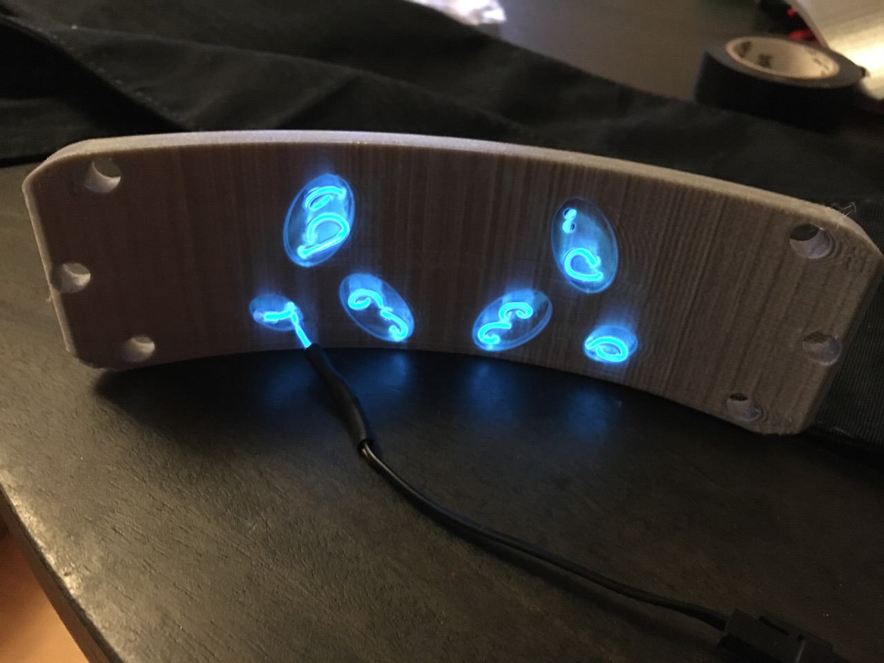
Here's the back again, but lit up this time.
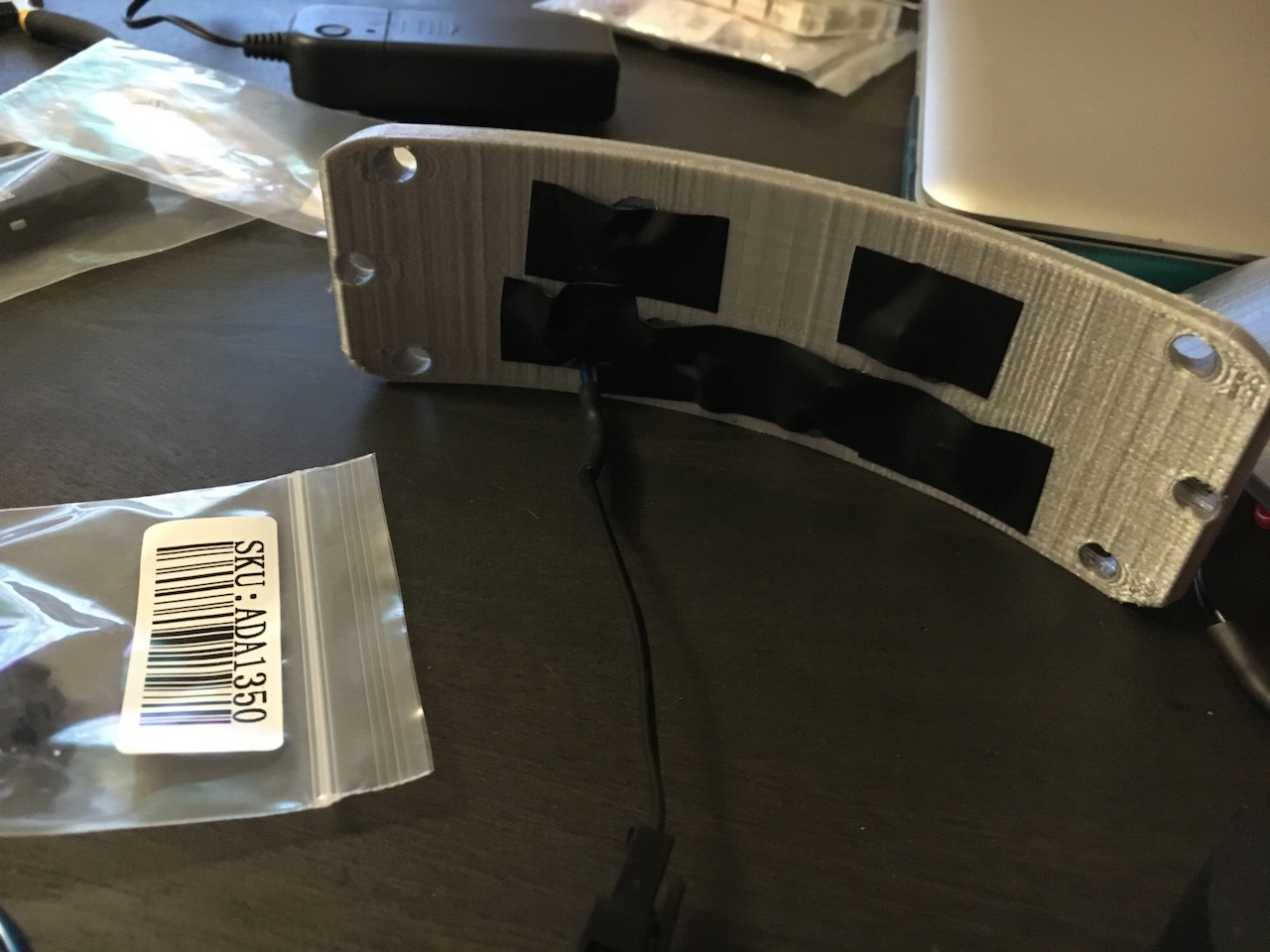
I'm not sure why I took that last photo, since I ended up covering the loops up with tape anyway to keep them from poking the wearer in the forehead.
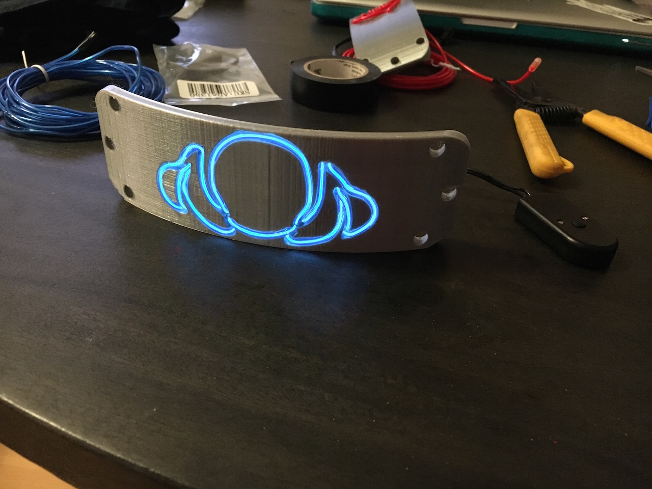
Not bad looking, if I do say so myself.
Attaching the plastic to the fabric was the most time consuming part for me... mostly because I am not incredibly proficient at sewing.
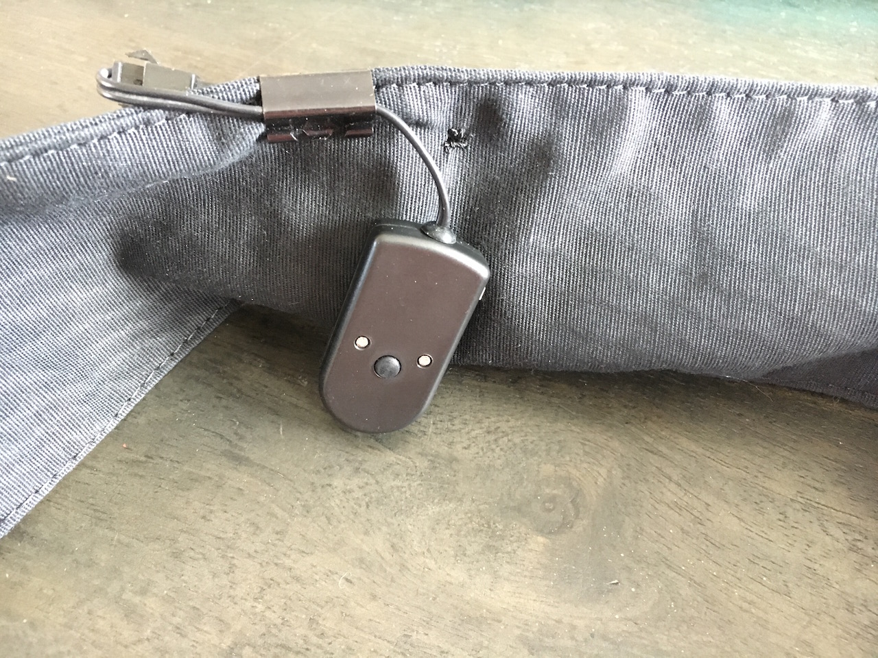
I attached a coin battery operated inverter to this headband via binder clip. It's small, lightweight, and provides power without interference 😀
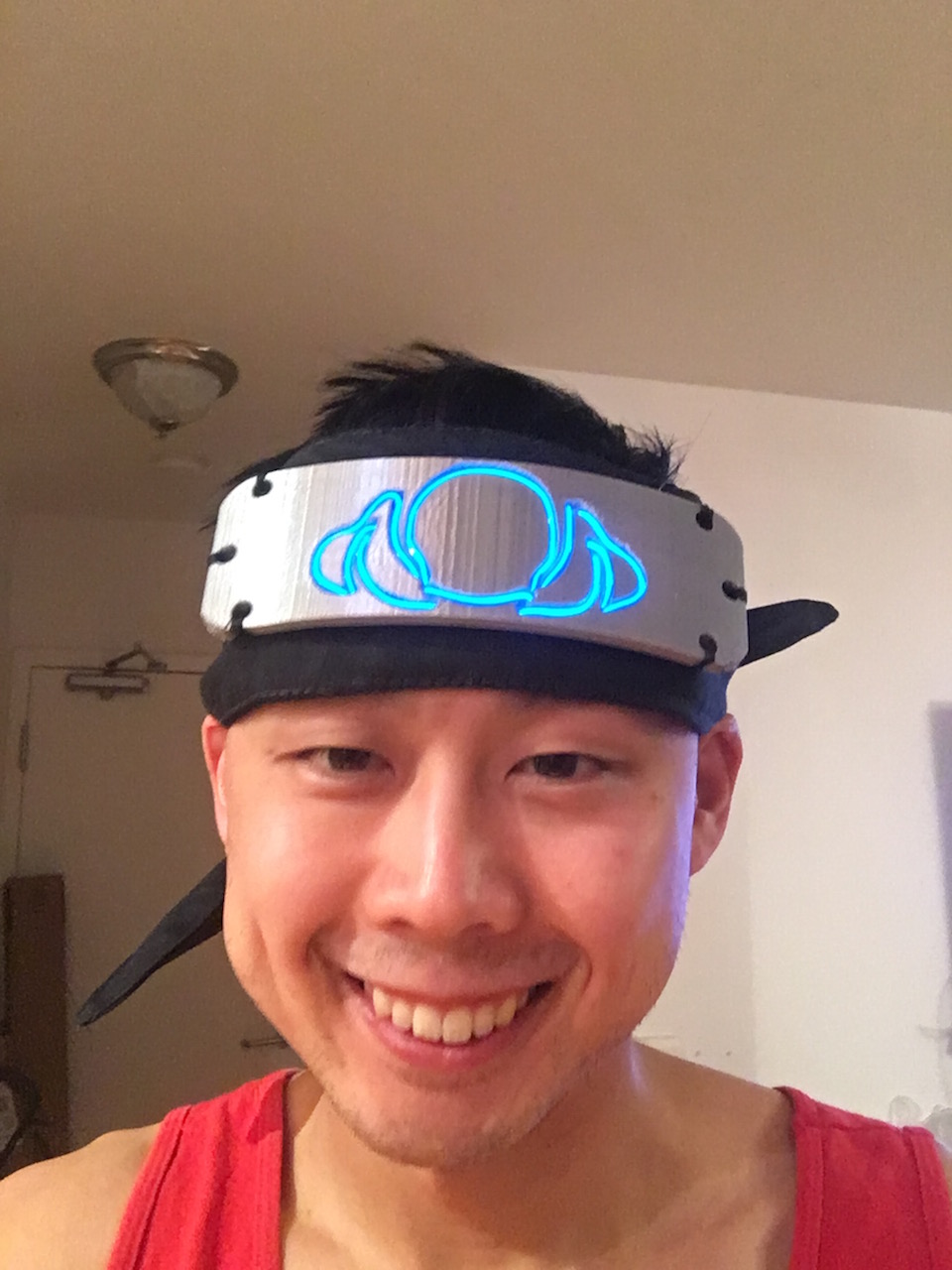
It fits!
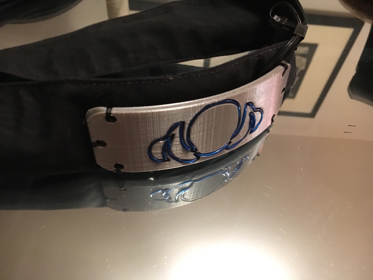
Glamour shot #1 on the infinity coffee table...
Glamour shot with 3 completed headbands
Strung
Lit
LIT!
3x headbands: strung, to lit, to LIT.
Prev
Next
Here’s a bonus gif, with a little preview of a flag project I’ve been working on as well…
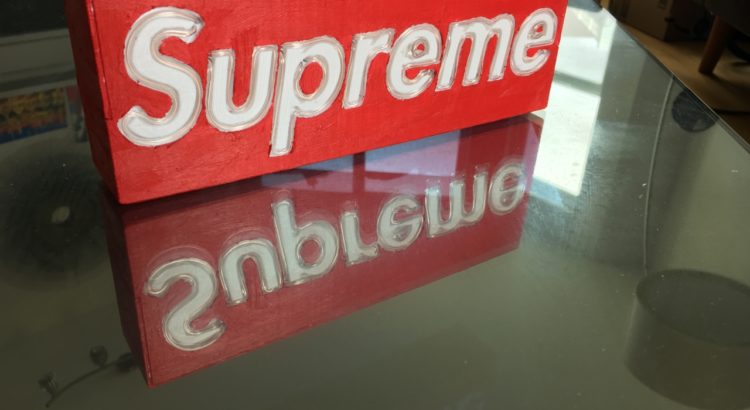
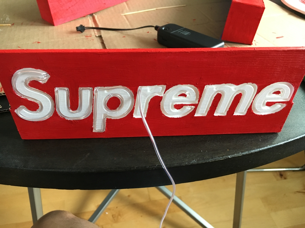
TL;DR: For my friend Teddy’s birthday, I made him a hypebeast worthy (if I
do say so myself) Supreme EL box.
My good friend Teddy is one of the biggest hypebeasts I know, so I wanted to
make something he would like. I went back to the EL wire well again for this
project (see: headbands https://www.andrewpip.com/2019/03/28/el-wire-lighted-headbands/
and sign <https://www.andrewpip.com/2019/04/07/faux-neon-signage>).
However, I needed to dig into my paint supplies dating all the way back to my
Iron Man Mask (https://www.andrewpip.com/2018/05/06/infinity-war-masks).
Conceptually, this project was relatively simple:
I made a box.
I cut some channel shaped holes in the box.
I painted the box.
I put my wire through the box.
I gave Teddy the box.
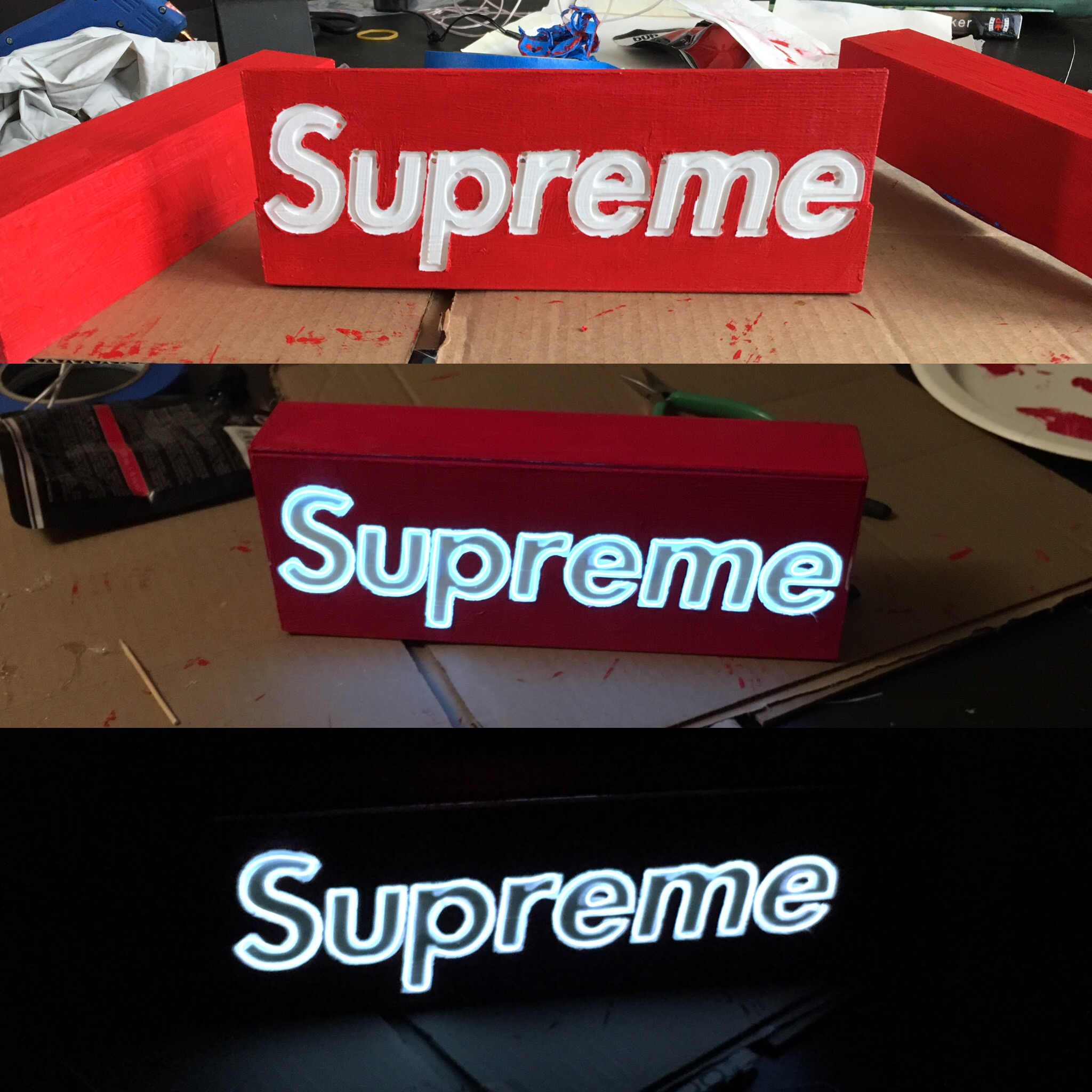
For this project, honestly I think the gallery will explain things better than I can in words, so here it is (it looks nicer if you click to open the full-sized images):
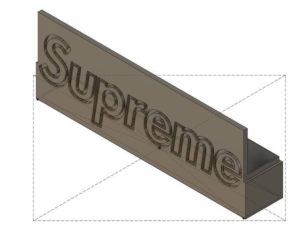
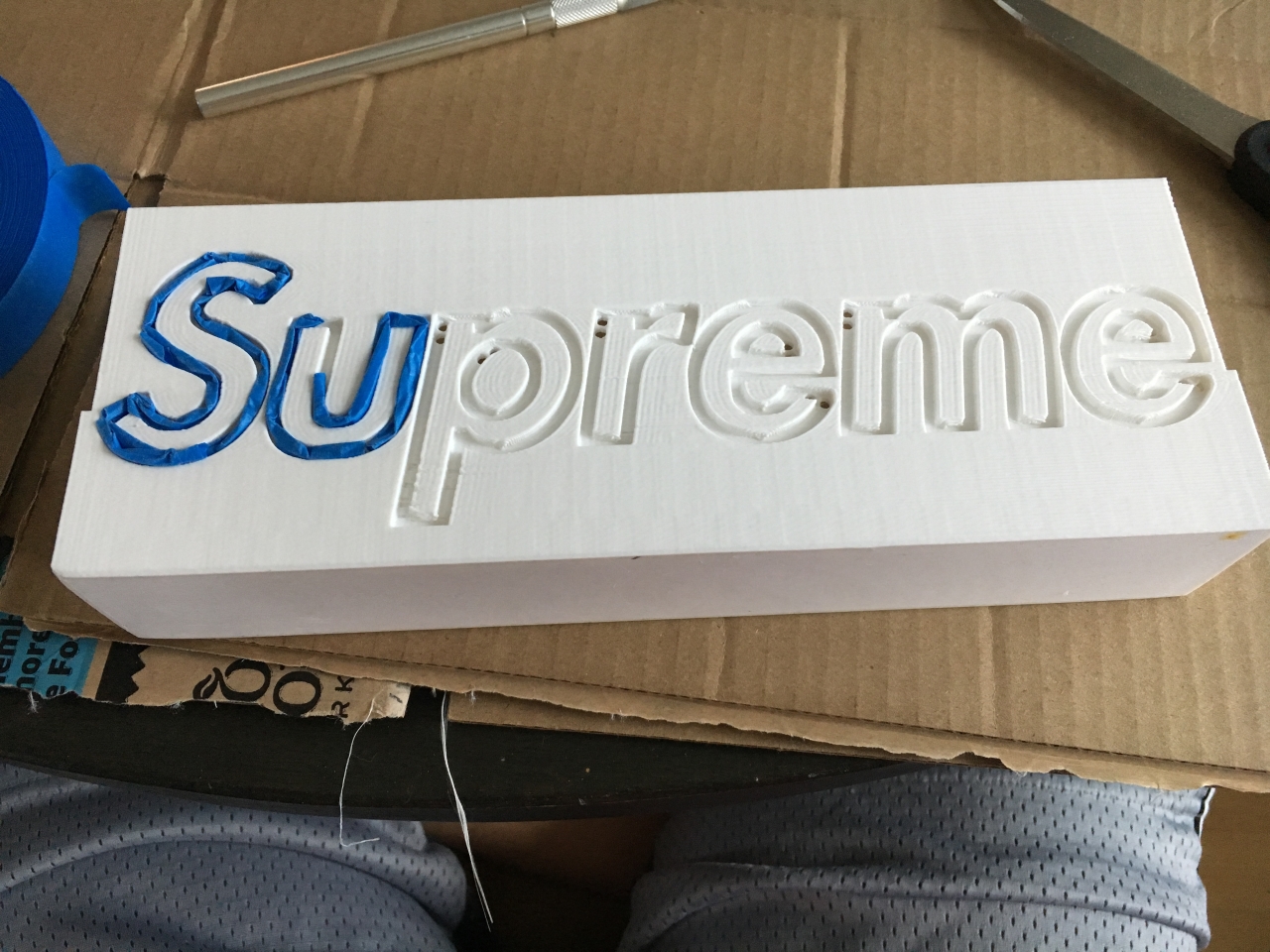
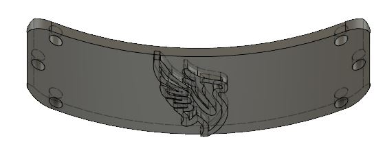
The outlined box shows the extents of my 3D printer's bed (200mm x 200mm). I wanted to make this single part as large as possible, so used a single master sketch to lay out all the features.
I used my layout sketch to extrude all of the basic box features very quickly. Completing a lot of the planning up front was a great time-saving investment.
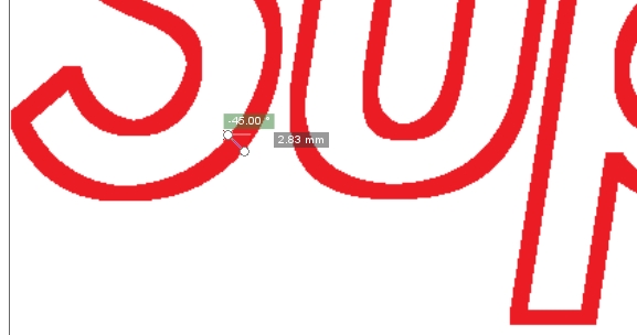
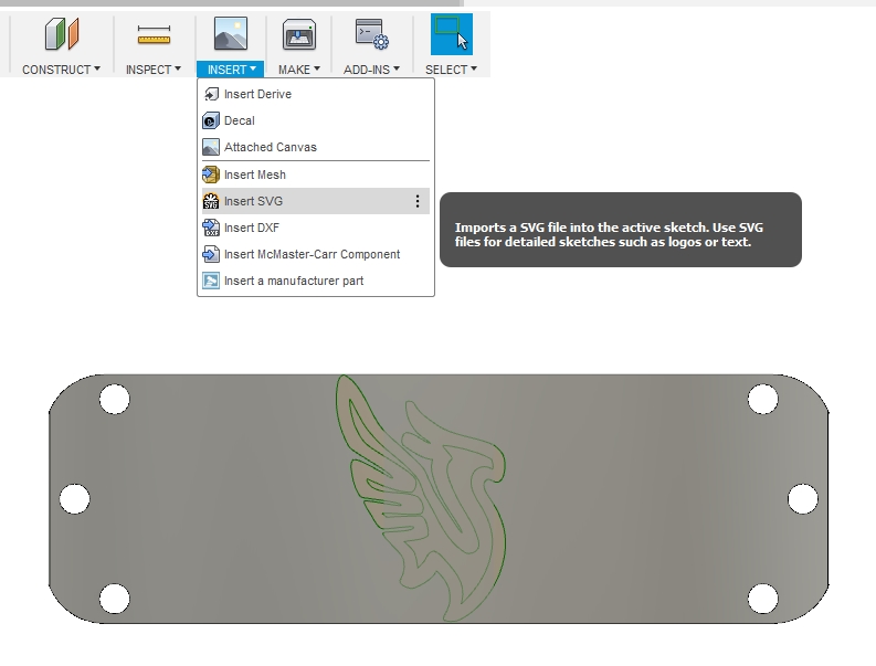
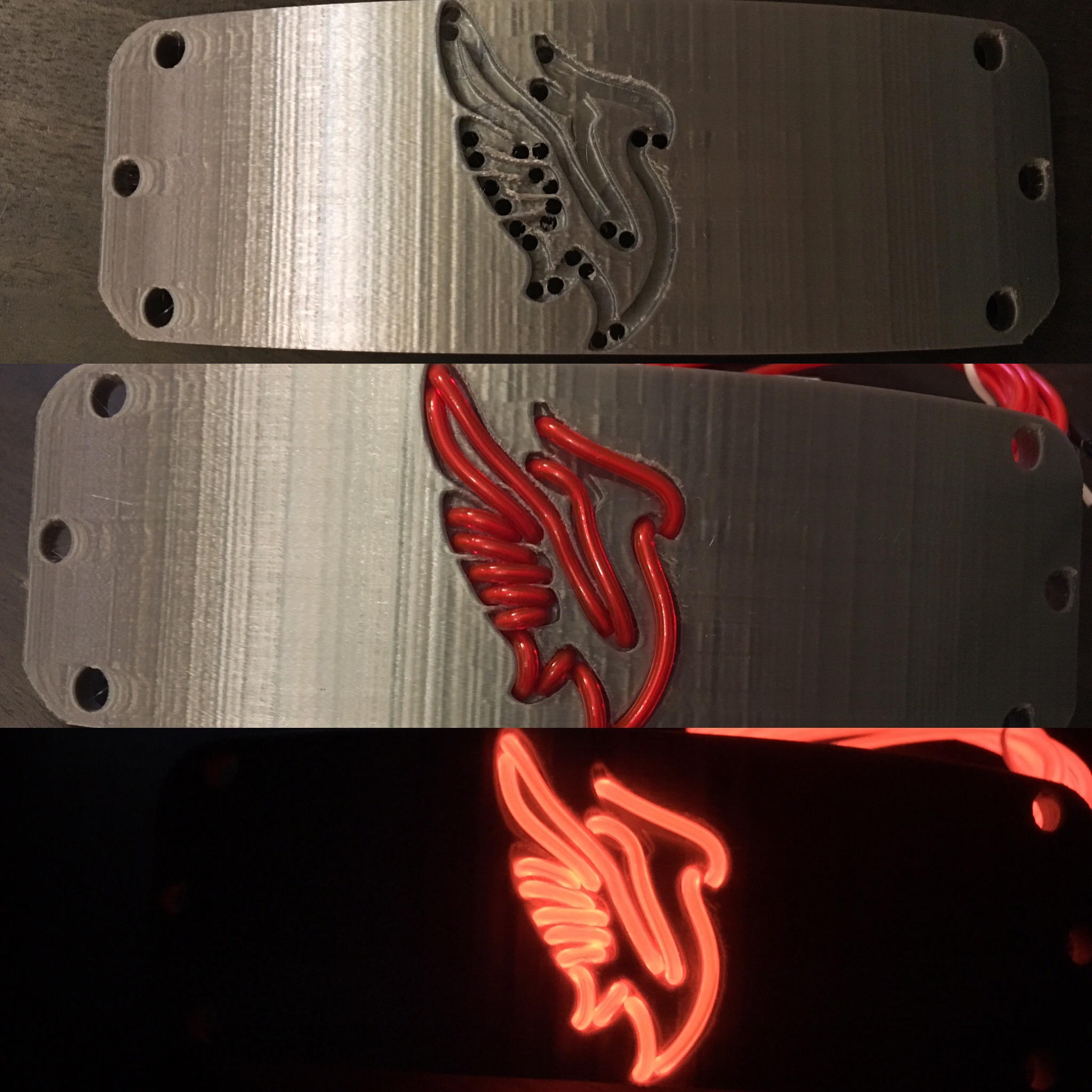
I created a stroked version of the logo in Gimp in a similar way to what I've done for previous projects. In Inkscape, I did some minor spacing and resizing tweaks to make sure the EL wire would fit well.
I inserted the SVG version of the logo and made a simple extruded cut.
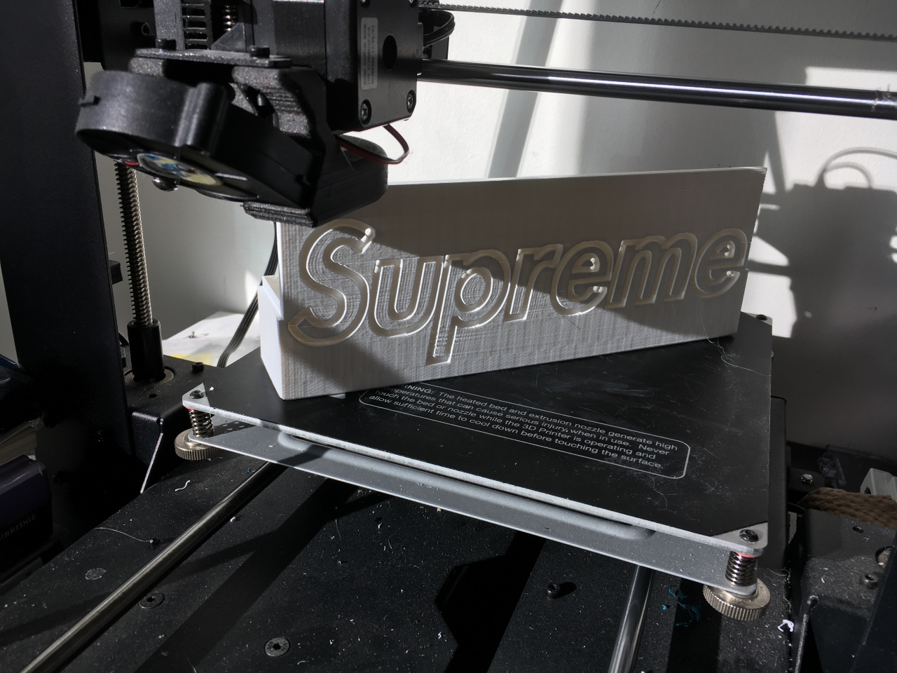
This print maximized my available print area, as planned. If you look closely, you can see where I placed the wire pass-thru holes.
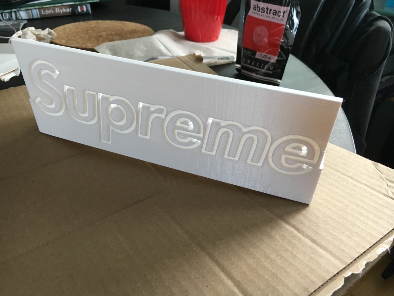
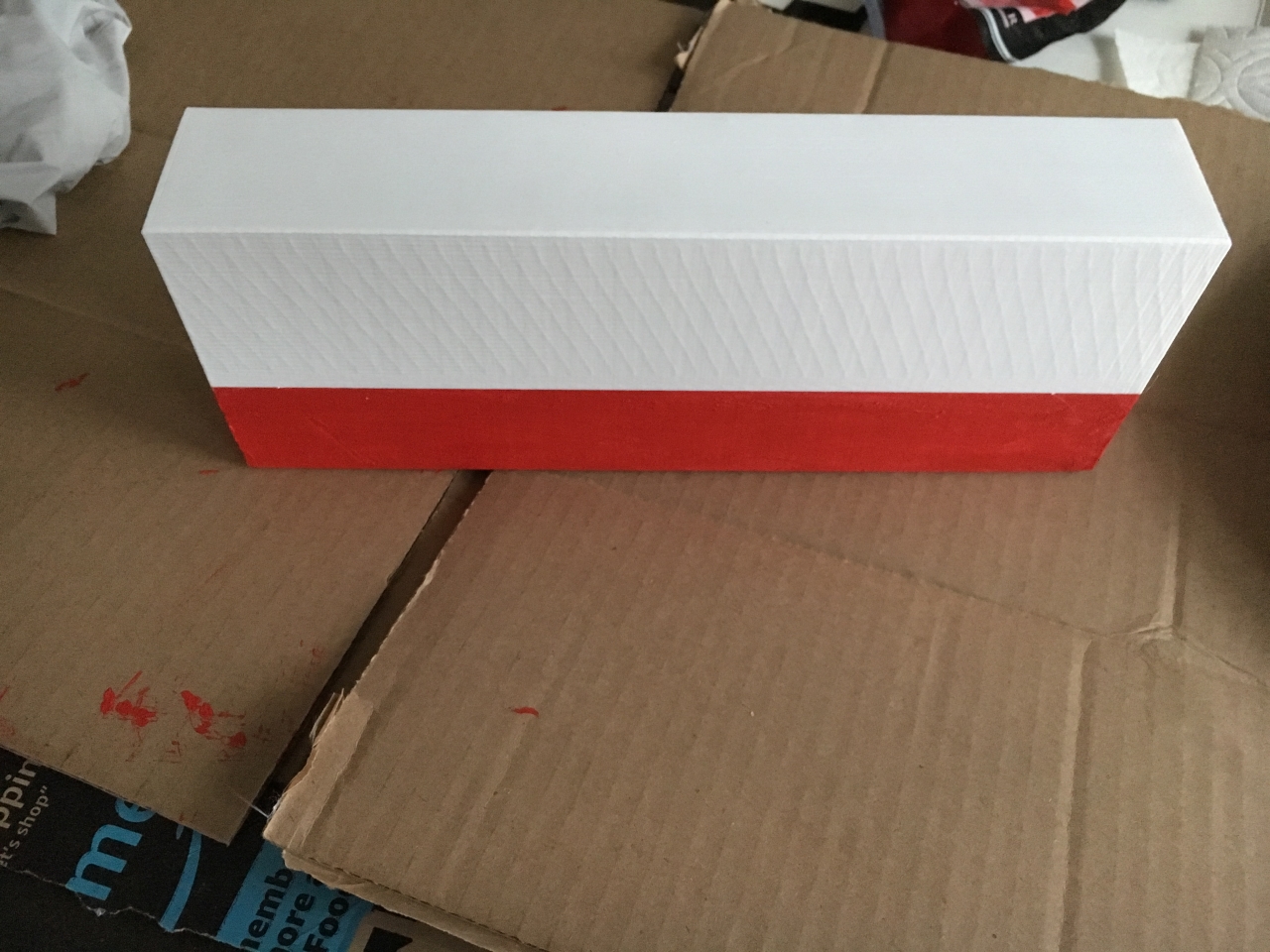
Off the printer, ready for painting...
Just kidding. I had to add a lot of masking to stop the paint from entering the channels and cross over into the lettering.
The masking took longer than I anticipated... If I were to redo this project, I would make this assembly into 3 pieces and just print the box in red PLA instead of trying to paint >.<
While I waited for the paint to dry, I printed the lid. Unfortunately it looks like I've got some printing artifacts that I need to address. Luckily, the paint ended up covering up most of this ugliness.
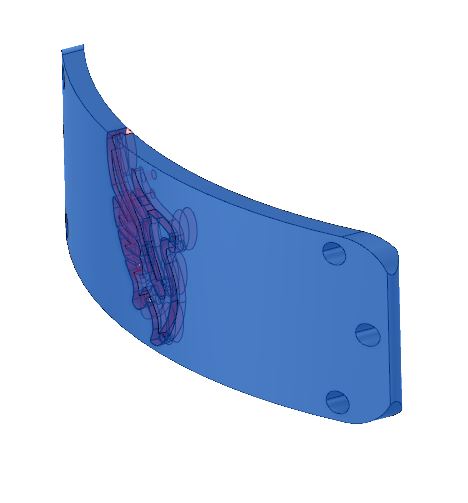
Here's the fit check of the lid from the front
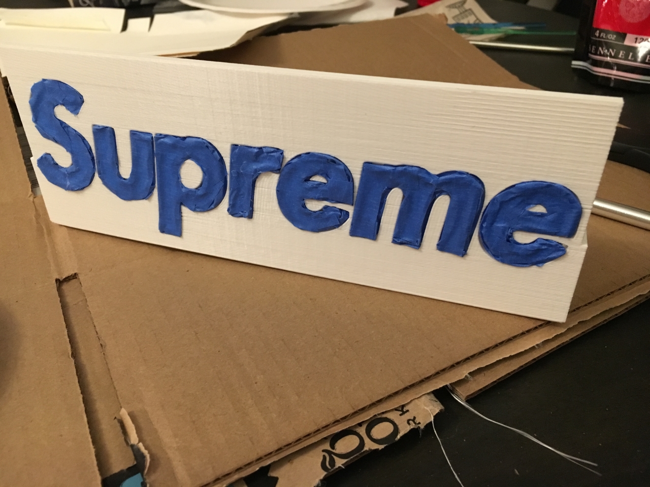
I peeled the blue tape mask off and started adding the EL wire. Not pictured is the steps where I went back in with a toothpick before this step to add/remove tiny specs of red paint where the masking was imperfect.
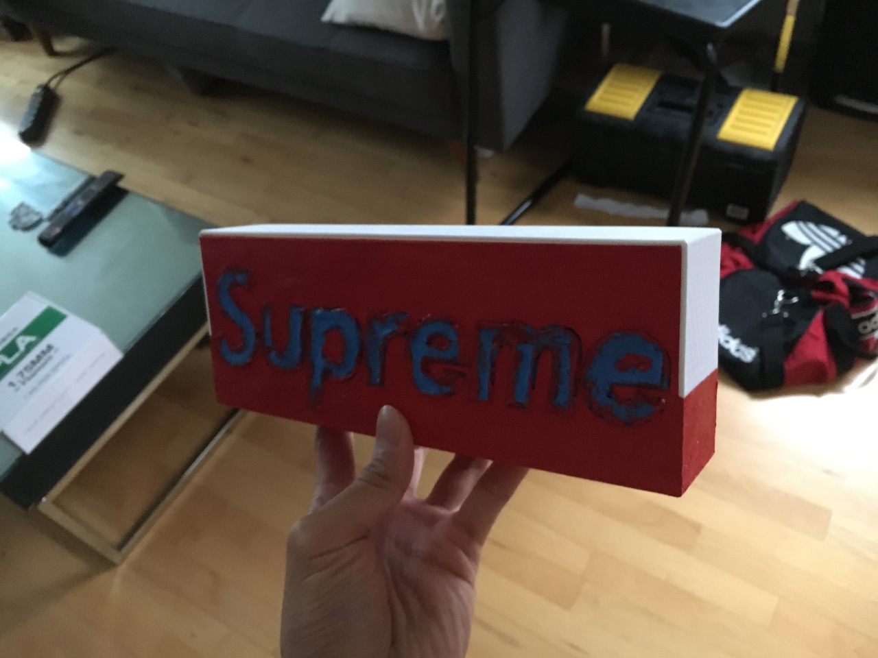
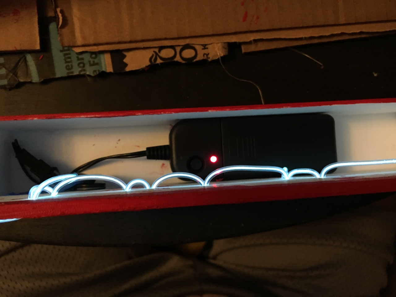
Here's a look inside the box after stringing--the control box fit inside perfectly... almost as if it was designed that way 😉
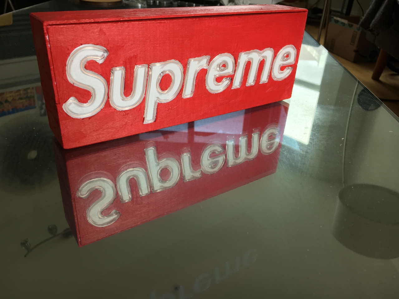
Here's a glamour shot... I ended up adding a bit of hot glue to help hold the central portions of the e's down.
The payoff was really worth it for this project. I really love how this box turned out... I think it looks even better in the dark!
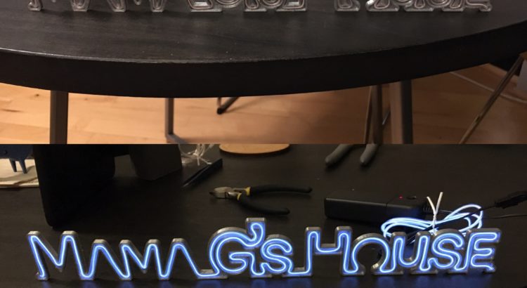
TL;DR: For my friend Gina’s birthday, I made her a faux-neon sign to
decorate her new condo with. I ended up making a few different versions of this
sign and through the process, I learned several useful tricks to speed up
vector image modifications, which will definitely make it easier for me going
forward.
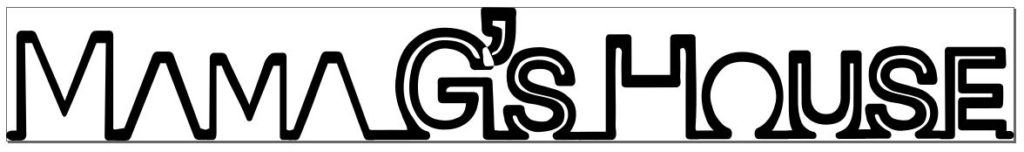
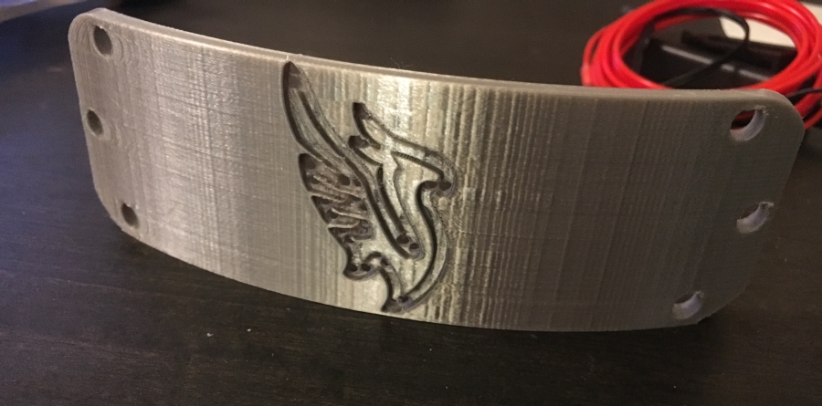
I continued playing with el wire since I bought so much for my headband project. Since my friend’s birthday was coming up, I figured it was a great opportunity to make something cool with it. I decided to make a faux-neon sign reading “Mama G’s House”.
I started by searching for neon sign fonts on google and downloaded a few to
try out including “Warnes”, “La Patio Script”, “I am online with u”, and
“Fenotype Neon”. All of them were free to download, but not all of them were
free for commercial usage, which is fine for this project as I’m not selling
it.
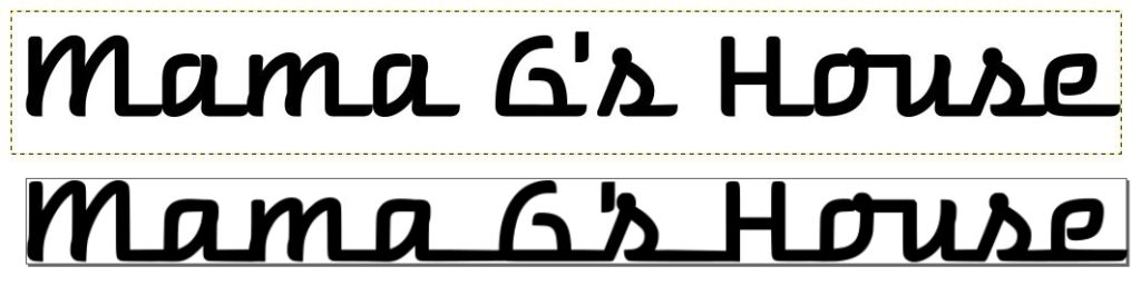
The first prototype I made used Warnes as the base font. I really liked how
the letters all connect at the bottom. However, I needed to do a bit of surgery
in Inkscape to connect the disparate words after vectorization:
The main modifications I made to this first font were just around connecting the letters and adjusting some of the spacing
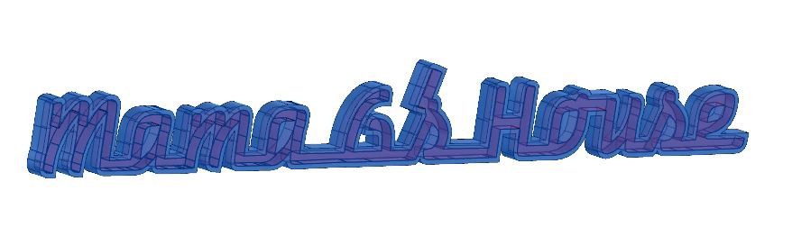
I imported the SVG directly into a sketch Fusion 360 and resized it to
ensure I had a ~3mm wide channel all over. Next, I modified the sketch to
remove areas near the bottom where the lettering overlapped. In a fashion
similar to what I did for the EL headbands, I extruded a positive model of the
letters. Next, I needed to move the apostrophe body and combine it with the
rest of the lettering. Then, I created a sketch, offset the entire object, and
cleaned up the line overlapping lines created by the offset tool. After
extruding the outlined body, I cut the positive lettering model out:
I reused the technique I discovered while making the EL headbands of cutting the positive channel from the main body
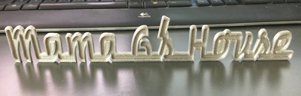
After slicing the STL in Cura, and waiting about 3 hours for production, the
print came out pretty well:
However, with the physical model in front of me, I saw the font I used had a
few issues. Primarily, although the channels I made fit the el wire, there were
too many places where stringing it required a double back, which was not
accounted for. Oops. Luckily, I hadn’t spent a lot of time on this, and I
figured Gina could still use it as a nice decoration even without lighting
effects.
The next font I tried was called “I am online with u” which had the
advantage of being a single connected line. Although this font was more ideal out
of the box, I still needed to tweak the vector version to make it work
properly. Essentially, I just modified the “corners” of the letters to allow
for more space wherever they changed direction, I adjusted the spacing between
words and letters, and I moved and combined the apostrophe to overlap with the
letters.
I modified this font a bit more heavily to ensure a good print. The biggest tweak was widening the letters where they changed direction so the EL wire could bend around.
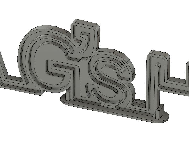
My workflow in Fusion 360 was essentially identical to the one I used for
the previous version of the sign: import svg, scale, and clean up sketch ->
extrude a positive channel -> offset the body and extrude the outline ->
use the combine tool to cut the positive channel away from the outlined body. Unfortunately,
this part was a bit too big to fit on my printer in one piece, so I needed to
split it into two. The split created a physical weakness which I shored up by
creating a small base to hold it together and help the entire assembly stand
upright.
The split was unfortunate but necessary to allow me to actually manufacture the sign. The base I made fit very well and helps keep the assembly standing too.
The print didn’t take very long—maybe about 4 hours in total for all the pieces. I was pretty happy with the results, and I think she was too 🙂
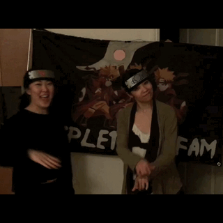
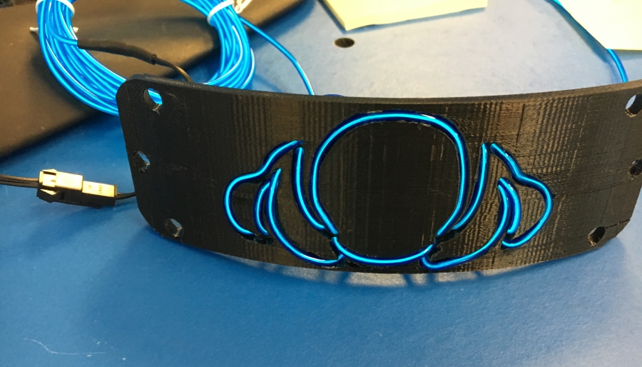
TL;DR: My friends asked me to make custom light up costume headbands for
them in the style of Naruto… so I did. I 3D printed channels through which I
fed electroluminescent wire to make logos of their favorite DJ’s. While the
project is simple in concept, I needed to dust off a bunch of tools I hadn’t
utilized in a while to complete it. While I’m not quite finished with these, I’m
too excited about how the project is looking NOT to share.
In the anime Naruto, the characters wear headbands to protect their
foreheads while they fight. My friends wanted ones that light up for their
costumes, and asked if I could help. If you want to skip over a lot of unnecessary
detail, just go to the gallery at the bottom where I put the build photos 😛
El wire is a fantastic way to add lighting effects to projects since it is
very bendable, easy to install, and does not require any programming at all
(just add power!). Before this project, I hadn’t played with electroluminescent
(el) wire for years, so I was excited to jump back in. The technology has
become a lot more common and widely available than I remember—there’re tons of
vendors for wire and the requisite DC to AC inverters. Unfortunately, the
inverters still make an annoying high pitched buzz whenever they’re on.
In terms of the mechanical design, the headband was very simple. I created a
base in Fusion 360 CAD to reuse in each version with a different logo. The
majority of my time has actually been spent optimizing the image preparation
pipeline. To go from a 2D-logo to a cut channel, the process I went through was
as follows:
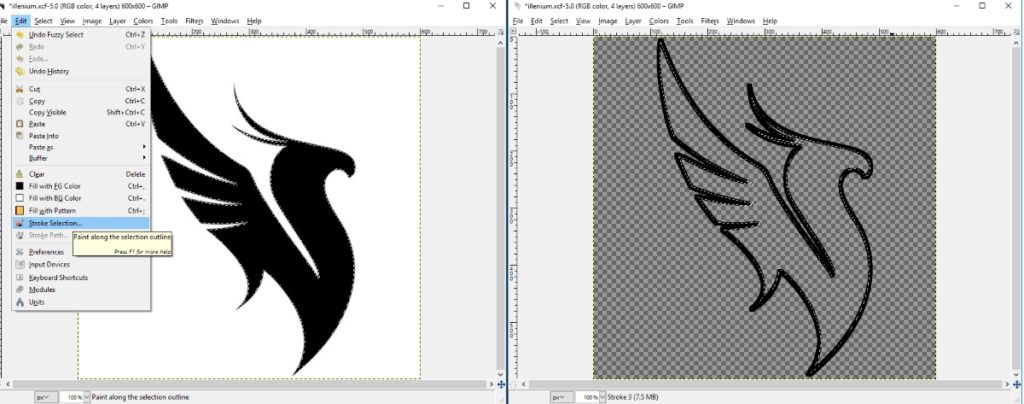
Prepare an outline image in Gimp (a free Photoshop competitor). The easiest way I found to do this was by using the fuzzy select tool to select the outline of the image I wanted to convert, then using the stroke selection tool.
Using stroke was key to getting a nice solid outline to begin my vector image with
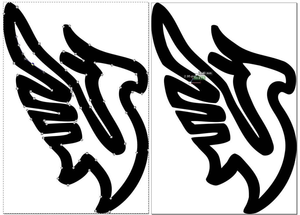
After saving the image as a bitmap in Gimp, I imported the file in Inkscape (similar to Adobe Illustrator) and stroked the bitmap to a path. I resized the vector image to fit my headband base, and manually edited the nodes until all parts of the path were approximately 2.5mm in width to fit my el wire.
I ended up doing quite a bit of manual manipulation to change the logo shape such that the 2.5mm channels would fit and still look somewhat like what I started with. Simple automatic offsetting didn’t work well at all.
Initially, I was exporting vector images as 2D
CAD-friendly DXF files. However, I made the groundbreaking discovery that
Fusion 360 actually lets you directly import and use SVG files. Using the
vector files (svg) directly is a lot more computationally friendly and MUCH
easier to work with. For example, the dxf version of the Illenium logo had
upwards of 670 line elements, whereas the svg file had two curves.
I can’t believe it took me so long to realize I could use SVG’s directly in Fusion 360… this was a gamechanger for my speed of productivity.
Within Fusion 360, I directly extruded the imported drawing.
Next, I did a few manipulations with the combine and move bodies menu to create
a “positive” model of the channel I wanted to CUT from the headband.
It’s a bit difficult to see, but I moved the positive cut out forward so it only intersects the model for the last 2.5mm of its extruded depth.
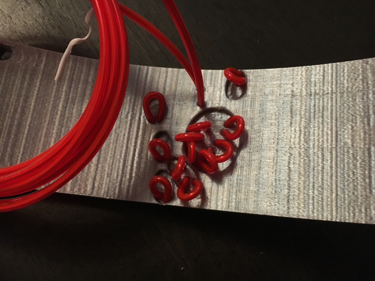
One of the limitations of working with el wire is that there is a minimum bend radius before you can actually break the wire and cause shorts. Unfortunately, since I was making headbands most of the detailed bends weren’t physically possible to make in a single piece. To maintain sharp edges required for the logo designs, I created pass through holes. This allows me to bend the wire in an unsightly loop where it can’t be seen in the final product. Positive models of the pass through holes were created by extruding cylinders from behind the headband up to the channel model.
Thru holes were simple extruded cylinders
Lastly, I created some “channels” on the back of the
headbands to accommodate the loops. In an early prototype, I created actual
channels out of spline sketches, but that proved to be a lot of work for no
reason. Now, I’ve simply created large inset areas that can fit the el wire
loops. It’s much less effort to achieve the same result. The positives for this
were extruded initially as separate bodies to the channels so I could shift
them backward about 0.8mm before joining to the rest of the positive channel
model.
I cut the positive channel model away from the base headband shape
A simple combine, export as STL, and slicing in Cura
resulted in a pretty decent print, if I do say so myself ;).
Here’s my first prototype blinking 😀
The first prototype I printed was in black PLA before I received this gorgeous silk silver shiny PLA made by Hatchbox on Amazon. I quickly realized that I didn’t have a great way of making the fabric for the bands since I don’t have any sewing skills. I am incredibly lucky to have super talented parents (check out my dad’s website here… he’s much more artistically talented than I am: www.bounsaypipathsouk.com) who are always willing to help. I Facetime called them to explain what I was making and mailed them my first sample. A few days later, I received some photos of my prototype solidly attached to a custom headband they made, and should receive them next week :D.
My parents were able to deliver!!
While there are still a few improvements left for me to make before I deliver
my final product, I’m pretty stoked at how well the project has turned out so
far, and just couldn’t wait to share.
As promised, here’s a gallery of the build:
My first prototype printed in black PLA strung and lit up before I shipped it to my parents to use as a template
I was pleasantly surprised at how shiny this silk silver PLA turned out. I'm also thankful I was able to print this without needing to dig support material out of the channels.
Backside of model fresh off the printer
The backside after stringing... my cutout areas need to be a bit bigger
Progression from fresh off the printer, to strung, to lit!
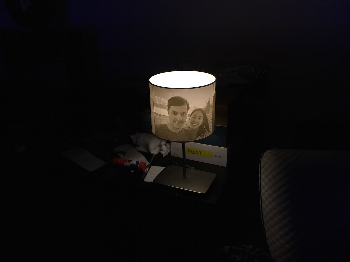
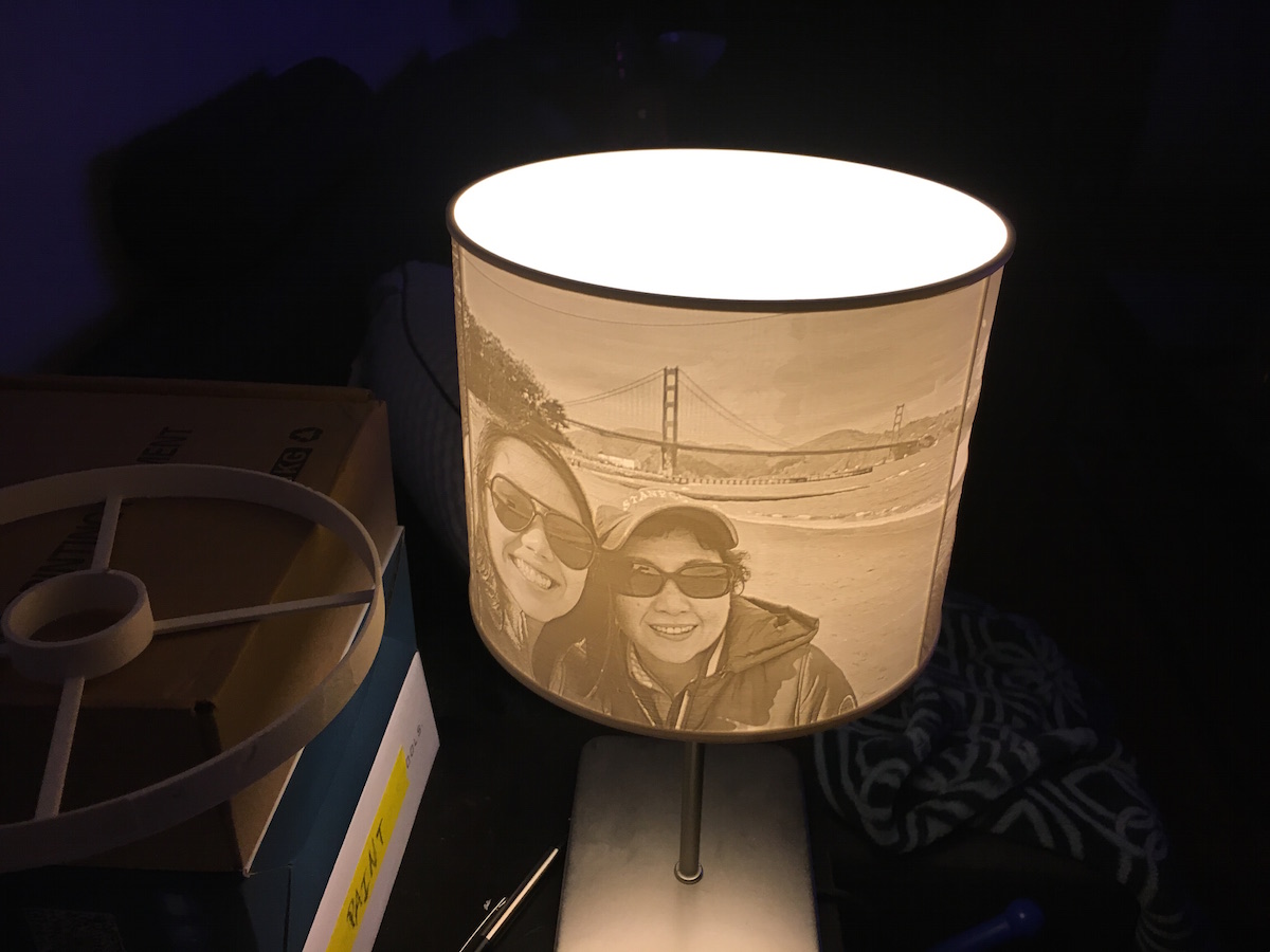
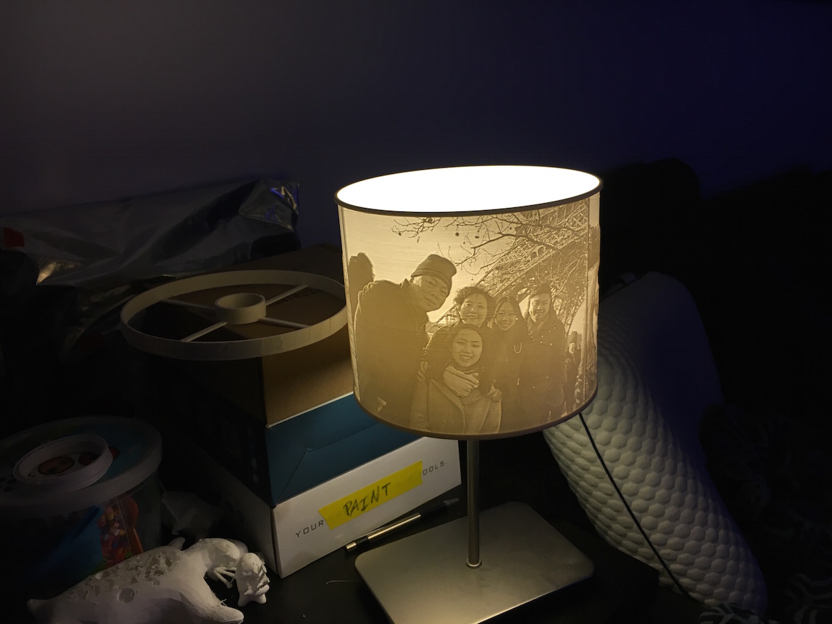
TL;DR: I made a lithophane lamp shade for my sister’s birthday. I used an
online tool that combined multiple images with specific measurements to create
a part that fit around my particular desk lamp. This was probably my longest
single part print to date—about 60 hours, but the results were well worth the
wait!
I continued playing around with lithophanes and made my sister a birthday
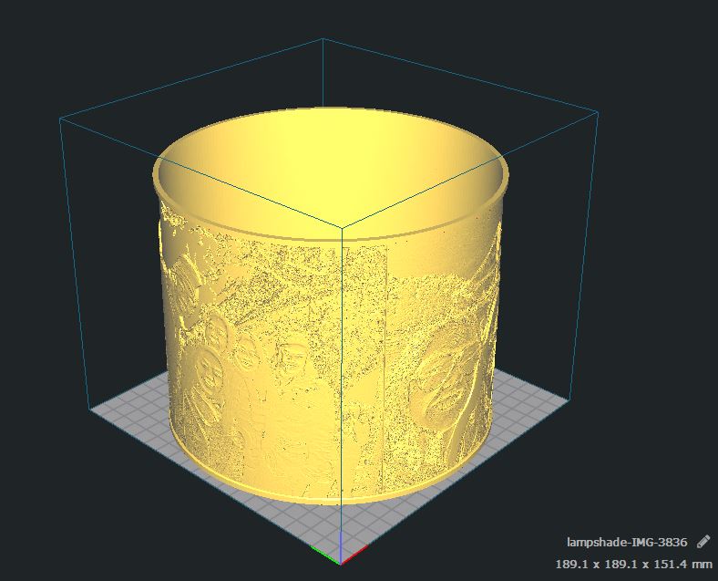
present—a litphophane lamp shade! I found another online tool at: https://www.lithophanemaker.com/Lamp%20Lithophane.html.
This one lets you enter various parameters to create an entire ready-to-print
part very quickly. While I would design this part a bit differently if I were
to do it from scratch, the speed of use was pretty undeniable.
I only had a two small hiccups—the size of the lamp retaining lip didn’t
quite match what I expected. That is—the cylinder turned out undersized for
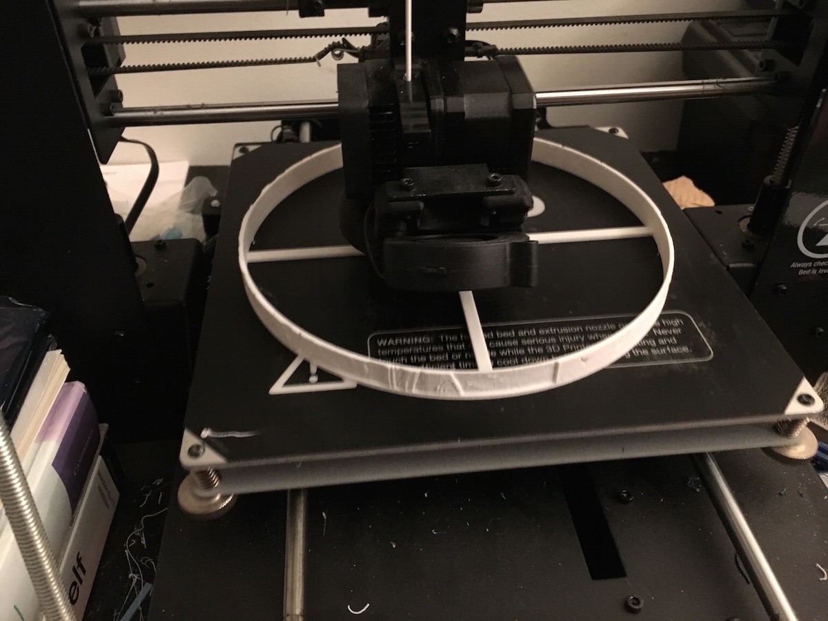
what I needed. Luckily, I had the foresight to first print only the inner
cylinder for a fit check. After I started the print the first time, I realized
that I forgot to add supports for the cylinder retaining lip to come out
properly, so I had to restart the print after a few hours >.<.
Once I started the print for real, I had the full lamp shade in hand after
about 60 hours. This was my longest single part print to date, and I think it
turned out incredibly well 😀
The gallery with descriptions below shows the process:
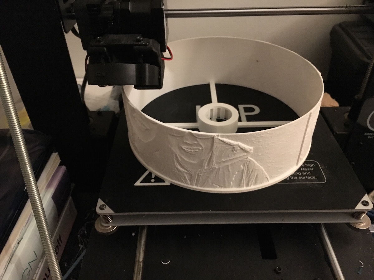
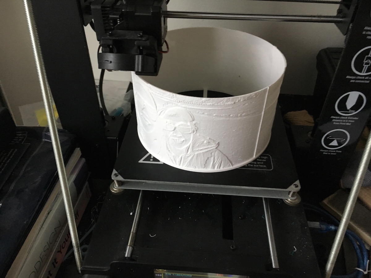
The lampshade took up nearly my entire print area :O. I was able to carry over my print settings from my previous lithophanes--0.12mm layer height, 100% infill, 60 mm/s print speed.
So the print begins...
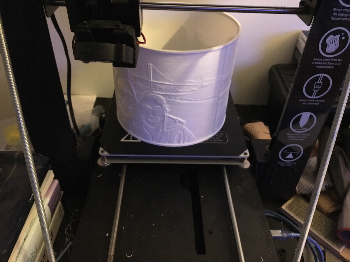
So the print continues...
... and the print continues...
About 60 hours later, the print is finally done!
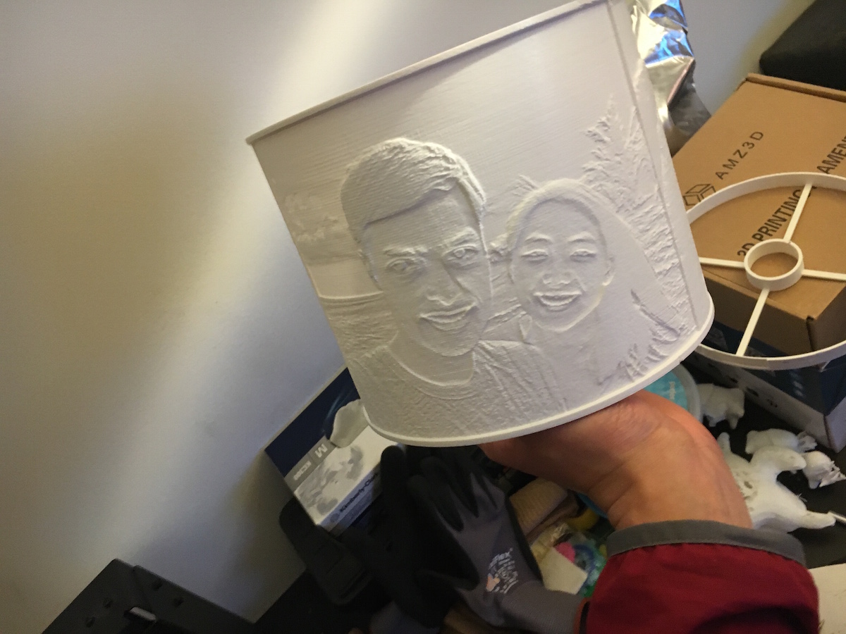
I was quite nervous getting the part off the printer--the spokes on the bottom looked a bit fragile, but it turned out surprisingly strong.
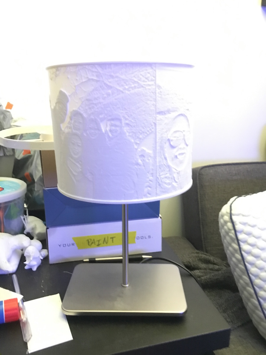
Here's the lamp shade mounted on the lamp. There's a simple clamp mechanism which holds the shade on the lamp cylinder.
I was surprised at how clear the images came out, even at a distance.
Here's the second image--the layer lines are pretty difficult to notice
Here's the third side, the layer lines are more noticeable on this photo, but I'm still very happy with it.
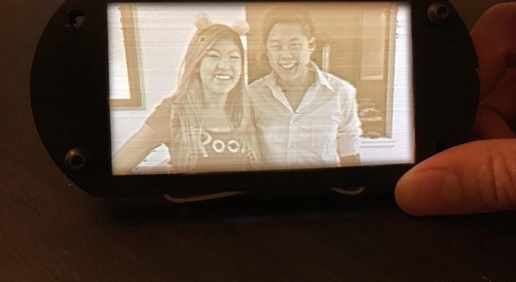
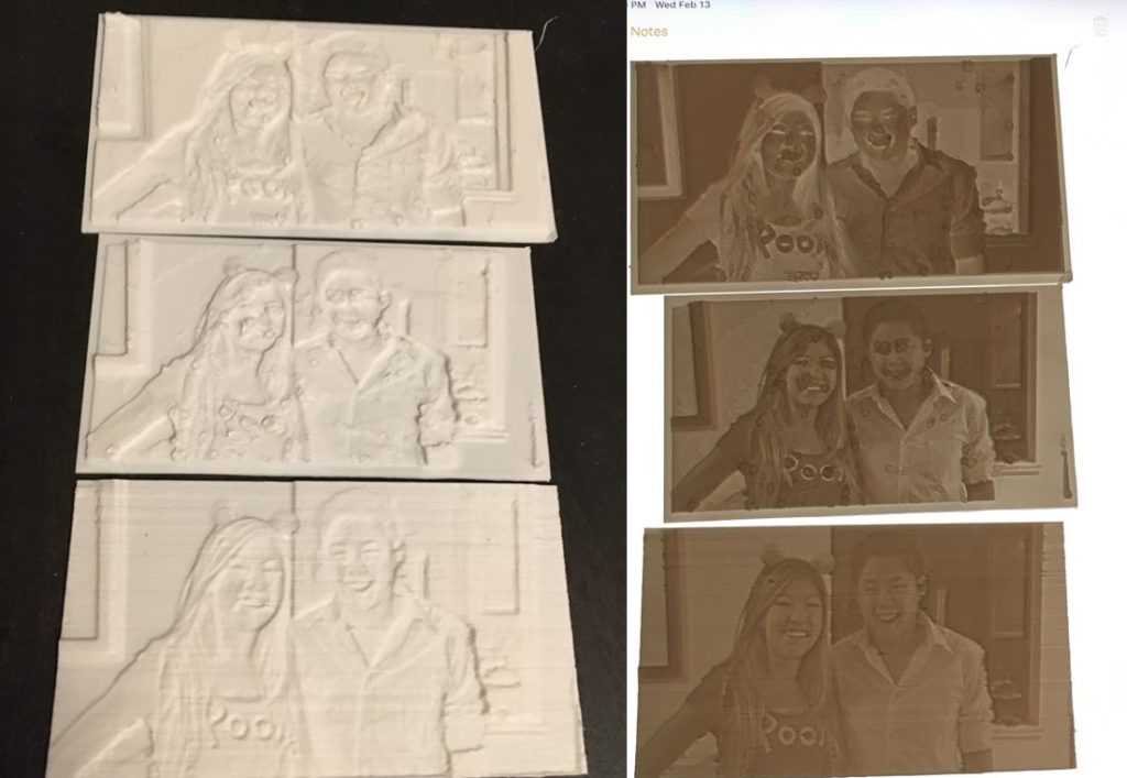
TL;DR: For Valentines Day, I made a lithophane—a 3D object which reveals an
image when light is shined through it. The operating principle is
basic—different “pixels” are created since thicker areas block more light.
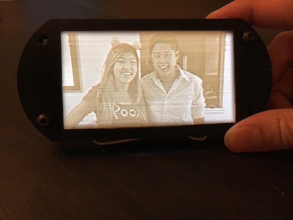
Lithophanes are really cool. Essentially, they’re 3D photos that physically encode pixels of an image by varying the amount of material. Thinner sections of the lithophane allow more light to pass through. I discovered a simple to use, yet highly customizable online lithophane generator at http://3dp.rocks/lithophane/. Upon making this discovery, my mind immediately went to the perler project I worked on last year… I saw I could reuse most of the components (back plate, switch, LED backlight), only making a new front plate. Since I designed the perler project housing in Onshape using top-down design principles, all the modifications only took a few minutes to complete and export for printing.
It took me three tries to finetune my print settings. In the first print, I
inadvertently made the image inverted:
My first attempt resulted in a scary looking inverted image… oops!
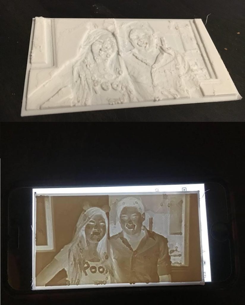
For the second print, I ended with a lot of blobs on our faces. Clearly this was because the nozzle dwelled a bit too long on the top surfaces since I printed this part flat on the bed:
My second attempt turned out nicer looking with the proper color inversion… but the blobs all over the place were less than ideal.
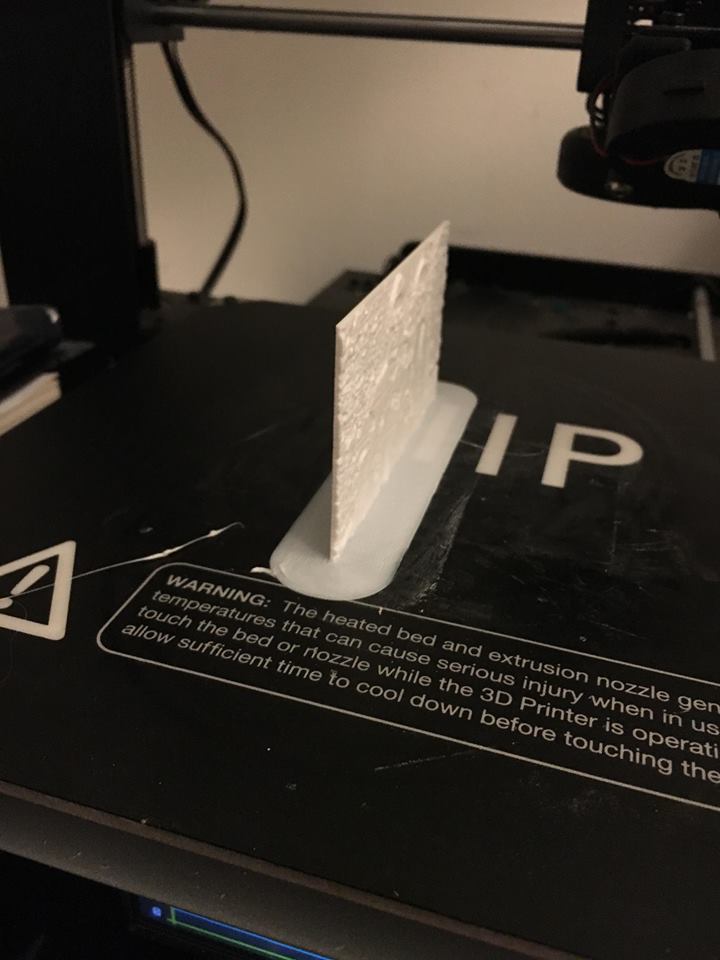
To correct for this, I reoriented the part on the print bed. I was worried
about the part falling over (hence my original print orientation), so I added a
really large brim to keep it rooted:
The 12mm brim I added, along with copious glue, helped keep the print from falling over
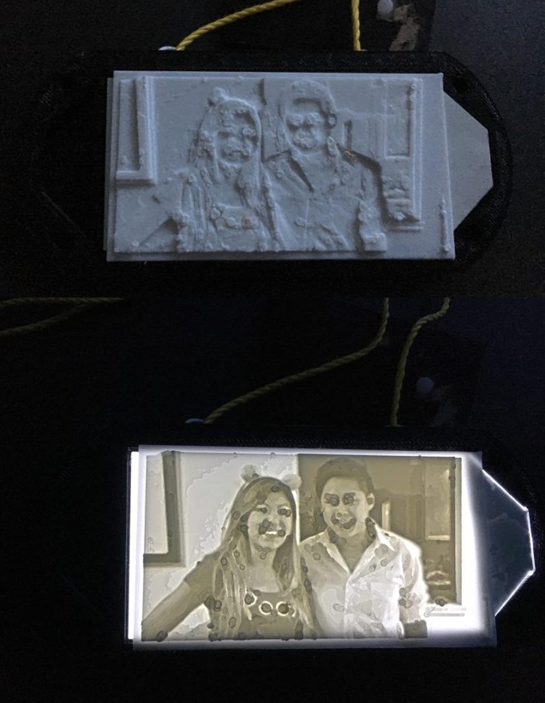
The third time really did turn out to be the charm, and I was very pleased
with how it turned out:
Success! Third time’s the charm 🙂
There’s a ton of ways in which the lithophane idea can be expanded and
improved upon. First, I need to redesign the housing unit to incorporate the
switch and battery. Others on the internet have wrapped lithophanes around
objects like cylinders to make custom lamps, trophies, and other neat projects.
The possibilities are endless… as you can see in the summary photo below, you
can use pretty much any light source and have the images turn out well:
It was very easy to progress pretty quickly since the parts were fast to print.
I’m excited to play around more with this type of stuff!